Yeastar Technology N412 Installation Manual
Hide thumbs
Also See for N412:
- User manual (104 pages) ,
- Installation manual (11 pages) ,
- Administrator's manual (106 pages)

Related Manuals for Yeastar Technology N412


Summary of Contents for Yeastar Technology N412
- Page 1 N412 Installation Guide N412 Installation Guide Version 1.0 Date: March 29, 2016 Yeastar Information Technology Co. Ltd. https://arttel.ru/shop/ip-ats/yeastar-n412...
-
Page 2: Table Of Contents
1. Preparation before Installation ................2 1.1 Packing List ......................2 1.2 Specifications and Operating Environment ............2 2. N412 Overview ......................3 2.1 N412 Front Panel ....................3 2.2 N412 Rear Panel ....................4 3. Installation ......................5 3.1 Placement Instructions ..................5 3.2 Connect Your N412 ...................5 Connection of Ethernet Ports .................... -
Page 3: About N412
12 analog extensions, 8 SIP extensions, and 4 SIP trunks. With Yeastar N412, small business can get business-class features with a compact and powerful analog and VoIP capable system. This Guide explains how to install Yeastar N412, how to log in Web interface, etc. https://arttel.ru/shop/ip-ats/yeastar-n412... -
Page 4: Preparation Before Installation
N412 Installation Guide 1. Preparation before Installation 1.1 Packing List Upon receiving Yeastar N412 gift box, please open the package and check if all the items are supplied as N412 Packing List. If there is any problem, please contact your provider. -
Page 5: N412 Overview
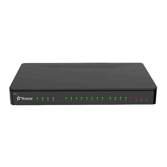
2. N412 Overview 2.1 N412 Front Panel POWER Line Status FXS Port Status Figure 2-1 N412 Front Panel Table 2-1 N412 Front Panel - LED Description LED Status Description The power is switched on. POWER The power is switched off. -
Page 6: N412 Rear Panel
Line Port EXT Port TF RESET Line Port Power Inlet Figure 2-2 N412 Rear Panel Table 2-2 N412 Rear Panels–Port Description Port Description Line Port For the connection of PSTN lines or ISDN BRI lines. EXT Port For connection of analog phones/fax machines. -
Page 7: Installation
3.2 Connect Your N412 Yeastar N412 is designed with 4 fixed S2 modules and 4 reserved slots to insert different modules according to your requirement. Unpack N412, you can see the N412 main board as Figure 3-1 shows. -
Page 8: Connection Of Ethernet Ports
Connection of Ethernet Ports Yeastar N412 provides two10/100M adaptive RJ45 Ethernet ports, LAN and WAN. Connect one end of a network cable to the LAN/WAN port of the N412, and the other end to any port of company’s switch/router. Connection of Line Ports N412 supports CO lines and ISDN BRI lines, to extend CO lines or BRI lines on N412, please insert the relevant O2 module or BRI module on N412. -
Page 9: Power Connection
N412 Installation Guide Power Connection Connect the power adapter to the N412’s power port, and then plug the power socket into an electrical outlet. The device will start booting. In the meantime, users would see that the “POWER” and “RUN” indicator lights turn on. -
Page 10: Network Settings
If the LAN port is connected to the company’s LAN, please configure the correct IP address and corresponding subnet mask. Note: please note that after changing the IP address of LAN port, N412 should be rebooted to make the new changes to take effect.
Need help?
Do you have a question about the N412 and is the answer not in the manual?
Questions and answers