
Related Manuals for Enthuze ENT5089


Summary of Contents for Enthuze ENT5089
- Page 1 Enthuze Automotive Products email: info@enthuze.ca website: www.enthuze.ca INSTRUCTIONS FOR ASSEMBLY AND USE OF ITEM: ENT5089 800 LBS UNIVERSAL OVER-CAB ALUMNIUM TRUCK RACK...
-
Page 2: Technical Specifications
Read and understand all warnings, cautions, and assembly, installation and use instructions prior to assembling, installing or using this product. Failure to follow all warnings, cautions and instructions may result in serious injury. The warnings, cautions, and instructions in this manual cannot cover all possible conditions or situations that could occur. - Page 3 PARTS LIST Prior to assembly and installation, make sure all parts are present, intact and undamaged. If you discover missing and/or damaged parts, please contact our customer service using the information on page 1. Item# Description Picture Quantity Item# Description Picture Quantity Crossbar...
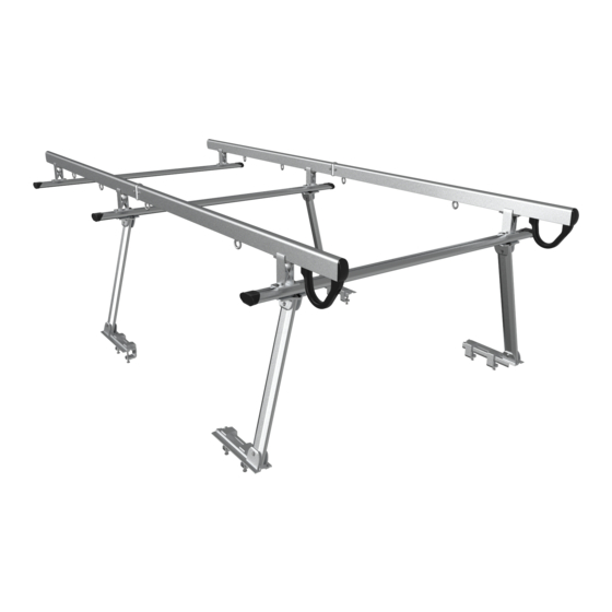
- Page 4 Tools Required Open Wrench (1 pc.) Allen Wrench (1 pc.) Tape Measure (1 pc) Size=17mm Size=6mm ASSEMBLY/PARTS DIAGRAM...
-
Page 5: Assembly Procedures
ASSEMBLY PROCEDURES Step 1: Support Arm Assembly ① ATTENTION! All M10x40 ② Connect Upper Connecting ③ Connect Driver Side Front Button Head Screws (15), require Plate (5), on Support Bar (2), and Leg Rail (3), & Lower Connecting a drop of thread glue (23), and secure with M10x40 Button Plate (6), to bottom of support installation/tightening within 2... - Page 6 STEP 2. Crossbar Installation ① Attach Spring Washers (20), ② Support arms are now ready ③ Slide the center channel of Flat Washers (21), to M10x25 for crossbar installation. the Crossbar (1), onto the M10 Button Head Screws (14), and Nuts (12), at the top of the secure to upper connecting plate support arms as shown.
- Page 7 STEP 3. Installation ① Attach an M10x75 Hex Head ② Position C-Clamp (7), close to ③ Tighten the M10x75 Hex Bolt (13), and M10 Hex Nut (19), the base of the support arm so Head Bolt (13), and the M10 Hex to each of the eight C-Clamps (7), that the tongue on the upper jaw Nut (19), until entire assembly is...
- Page 8 STEP 4. Side Rail Assembly and Installation ① Attach plastic sleeve (27), to ② Attach Connecting Plate (22), ③ Attach Splint (24), and end of Side Rail (9), as shown. to end of Side Rail (9), using Thread Block (30), to one end of M10x16 Button Head Screw (32), Side Rail (9), using M10x16 Spring Washer (20), and Washer...
- Page 9 ⑨ Attach side rail assemblies to crossbars using ⑩ Tighten all 16 of the M10x25 Button Head M10x25 Button Head Screws (14), Spring Washers Screws (14), on the four Connecting Bases (11), (20), Flat Washers (21), and M10 Nuts (12). Do linking the side rails to the two rear crossbars not tighten until both side rails assemblies are prior to installing and securing the front-most...
- Page 10 ③ Check to make sure all hardware has been securely tightened. Depending on the configuration of your truck, your installed rack should resemble this diagram. Congratulations, your rack is now ready for use. Please remember to haul your loads safely.
Need help?
Do you have a question about the ENT5089 and is the answer not in the manual?
Questions and answers