Carrier 38AK007 Installation, Start-Up And Service Instructions Manual
Air-cooled condensing units 50/60 hz
Hide thumbs
Also See for 38AK007:
Table of Contents
Advertisement
CONTENTS
SAFETY CONSIDERATIONS . . . . . . . . . . . . . . . . . . . 1
INSTALLATION . . . . . . . . . . . . . . . . . . . . . . . . . . . . . 1-8
• UNCRATE UNIT
• INSPECT SHIPMENT
• CONSIDER SYSTEM REQUIREMENTS
Step 2 - Rig and Mount the Unit . . . . . . . . . . . . . 4
• COMPRESSOR MOUNTING
Step 3 - Complete Refrigerant Piping
Connections . . . . . . . . . . . . . . . . . . . . . . . . . . . . . . . 4
• SIZE REFRIGERANT LINES
Step 4 - Make Electrical Connections . . . . . . . . 6
• FIELD POWER SUPPLY
• FIELD CONTROL WIRING
START-UP . . . . . . . . . . . . . . . . . . . . . . . . . . . . . . . . . . 9,10
Preliminary Checks . . . . . . . . . . . . . . . . . . . . . . . . . . 9
Evacuate and Dehydrate . . . . . . . . . . . . . . . . . . . . . . 9
Refrigerant Charge . . . . . . . . . . . . . . . . . . . . . . . . . . . 9
Compressor Overload . . . . . . . . . . . . . . . . . . . . . . . . 9
Cycle-LOC™ Device . . . . . . . . . . . . . . . . . . . . . . . . . . 9
High-Pressure Switch (HPS) . . . . . . . . . . . . . . . . . 10
Time Guard II Device . . . . . . . . . . . . . . . . . . . . . . . 10
Refrigerant Service Ports . . . . . . . . . . . . . . . . . . . 10
Cooling . . . . . . . . . . . . . . . . . . . . . . . . . . . . . . . . . . . . . 10
Sequence of Operation . . . . . . . . . . . . . . . . . . . . . . 10
Oil Charge . . . . . . . . . . . . . . . . . . . . . . . . . . . . . . . . . 10
SERVICE . . . . . . . . . . . . . . . . . . . . . . . . . . . . . . . . . . 11,12
Cleaning . . . . . . . . . . . . . . . . . . . . . . . . . . . . . . . . . . . . 11
Lubrication . . . . . . . . . . . . . . . . . . . . . . . . . . . . . . . . . 11
Condenser-Fan Adjustment . . . . . . . . . . . . . . . . . . 11
Capacity Control - Unit 38AKS012 Only . . . . . 12
Compressor Removal . . . . . . . . . . . . . . . . . . . . . . . 12
Crankcase Heater . . . . . . . . . . . . . . . . . . . . . . . . . . . 12
TROUBLESHOOTING GUIDE . . . . . . . . . . . . . . . 13,14
START-UP CHECKLIST . . . . . . . . . . . . . . . CL-1, CL-2
SAFETY CONSIDERATIONS
Installing and servicing air-conditioning equipment can be
hazardous due to system pressure and electrical compo-
nents. Only trained and qualified service personnel should
install or service air-conditioning equipment.
When working on air-conditioning equipment, observe pre-
cautions in literature and on tags and labels attached to unit.
Manufacturer reserves the right to discontinue, or change at any time, specifications or designs without notice and without incurring obligations.
Book 1 4
PC 111
Tab
3a 2a
Installation, Start-Up and
Service Instructions
Page
Catalog No. 533-876
Printed in U.S.A.
38AK007,008,012
38AKS008,009,012
Air-Cooled Condensing Units
Follow all safety codes. Wear safety glasses and work gloves.
Use quenching cloth for brazing operations. Have fire ex-
tinguisher available. Read these instructions thoroughly. Con-
sult local building codes and National Electrical Code (NEC)
(U.S.A. Standard) for special installation requirements.
Before installing or servicing system, always turn off
main power to system. There may be more than one
disconnect switch. Electrical shock can cause personal
injury.
INSTALLATION
The 38AK007, 008, and 012 units use hermetic compres-
sors. The 38AKS008, 009, and 012 units use semi-hermetic
compressors. See Table 1A or 1B for physical data.
Step 1 - Complete Pre-Installation Checks
UNCRATE UNIT (See Fig. 1) - Remove unit packaging
except for the top skid assembly and wood bumpers, which
should be left in place until after unit is rigged into place.
INSPECT SHIPMENT - File claim with shipping com-
pany if shipment is damaged or incomplete.
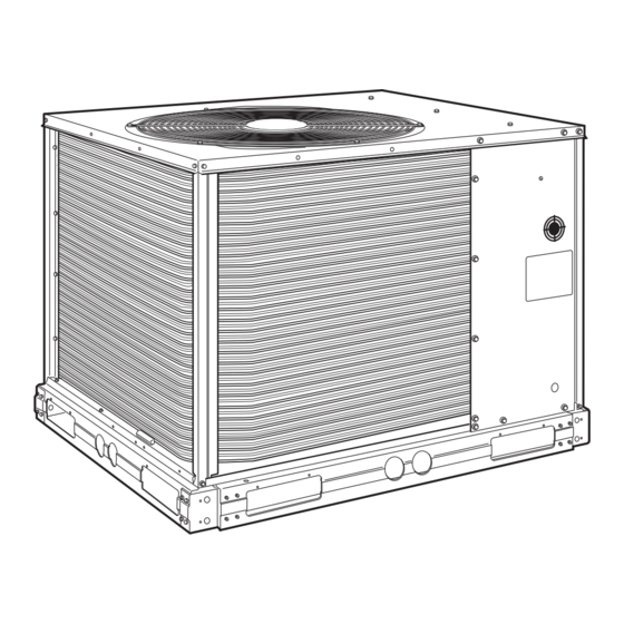
Fig. 1 - Model 38AK (Size 007 Shown)
Form 38A-7SI
Pg 1
50/60 Hz
5-99
Replaces: 38A-6SI
Advertisement
Table of Contents

Related Manuals for Carrier 38AK007


Summary of Contents for Carrier 38AK007
-
Page 1: Table Of Contents
Electrical shock can cause personal injury. INSTALLATION The 38AK007, 008, and 012 units use hermetic compres- sors. The 38AKS008, 009, and 012 units use semi-hermetic compressors. See Table 1A or 1B for physical data. Step 1 — Complete Pre-Installation Checks UNCRATE UNIT (See Fig. - Page 2 Table 1A — Physical Data — 50/60 Hz (English) UNIT 38 OPERATING WEIGHT (lb) Aluminum Coils (Standard) Copper Coils (Optional) RIGGING WEIGHT (lb) Aluminum Coils (Standard) Copper Coils (Optional) REFRIGERANT* COMPRESSOR Bristol, Reciprocating Quantity...Type 1...H26A72Q Quantity Cylinders Speed (rpm) — 60 Hz —...
-
Page 3: Motor Hp (Nema) 1
UNIT 38 AK007 OPERATING WEIGHT (kg) Aluminum Coils (Standard) Copper Coils (Optional) RIGGING WEIGHT (kg) Aluminum Coils (Standard) Copper Coils (Optional) REFRIGERANT* COMPRESSOR Bristol, Reciprocating Quantity...Type 1...H26A72Q Quantity Cylinders Speed (r/s) — 60 Hz — 50 Hz Oil Charge (L) CONDENSER FAN —... -
Page 4: Step 2 - Rig And Mount The Unit
See Table 4A and 4B and also refer to Part 3 of Carrier System Design Manual for design details and line sizing. Refer to air handler in- stallation instructions for additional information. - Page 5 UNIT 38 DIM. A DIM. B DIM. C 1 -6 ⁄ 1 -2 ⁄ — AK007 [470.0] [375.0] — 1 -8 1 -6 ⁄ — AK008 [508.0] [470.0] — 1 -9 1 -8 2 -0 AK012 [533.4] [508.0] [609.6] 1 -6 1 -4 ⁄...
-
Page 6: Connections
Table 5, Note 2, to determine the percent voltage imbalance. Operation on improper line voltage or excessive phase im- balance constitutes abuse and may cause damage to elec- trical components. Such operation would invalidate any ap- Max Allowable plicable Carrier warranty. Temp Loss 208/230-3-60 Max Allowable 380-3-60... - Page 7 UNIT NOMINAL VOLTAGE (V-Ph-Hz) 208/230-3-60 460-3-60 AK007 575-3-60 220-3-50 400-3-50 208/230-3-60 460-3-60 AK008 575-3-60 220-3-50 400-3-50 208/230-3-60 460-3-60 AK012 575-3-60 220-3-50 400-3-50 208/230-3-60 380-3-60 460-3-60 AKS008 575-3-60 220-3-50 400-3-50 208/230-3-60 380-3-60 460-3-60 AKS009 575-3-60 220-3-50 400-3-50 208/230-3-60 380-3-60 460-3-60 AKS012 575-3-60 220-3-50 400-3-50...
- Page 8 FIELD CONTROL WIRING — Install a Carrier-approved accessory thermostat assembly according to installation instructions included with the accessory. Locate thermostat assembly on a solid wall in the conditioned space to sense average temperature in accordance with thermostat instal- lation instructions.
-
Page 9: Start-Up
Evacuate and Dehydrate — drate entire refrigerant system by use of the methods described in Carrier GTAC II, Module 4, System Dehydra- tion. Evacuate system down to 500 microns and ensure vacuum hold for 15 minutes. If vacuum does not hold, pressurize sys- tem and locate leak and repair. -
Page 10: High-Pressure Switch (Hps)
38AKS UNITS — Allow unit to run for about 20 minutes. Stop unit and check compressor oil level. Add oil only if necessary to bring oil into view in sight glass. Use only Carrier- approved compressor oil. Approved oils are:... -
Page 11: Service
Fig. 11 — Propping Up Top Panel Fig. 12 – Separating Coil Sections NOTE: Fan height adjustments are as follows: UNIT 38AK007 (60 Hz) All 50-Hz Units All 60-Hz Units (Except 38AK007) Fig. 13 — Condenser-Fan Adjustment 3. Loosen fan hub setscrews. -
Page 12: Capacity Control - Unit 38Aks012 Only
1. Shut off power to unit. Remove unit access panel (front of unit). 2. Remove refrigerant from system using refrigerant removal methods described in the Carrier GTAC-II, Module 5, Charging, Recovery, Recycling, and Reclamation. 3. Disconnect compressor wiring at compressor terminal box. -
Page 13: Troubleshooting Guide
Remove obstruction, clean condenser coil. Air recirculating. Clear airflow area. Noncondensables in system. Recover, evacuate and recharge as required. Refer to Carrier GTAC-II, Module 5, Charging, Recovery, Recycling, and Reclamation. Refrigerant overcharge. Recover as required. Refrigerant system restrictions. Check or replace filter drier, expansion valve, etc. - Page 14 Fig. 15 — Typical 38AK Component Arrangement Fig. 16 — Typical 38AKS Component Arrangement Copyright 1999 Carrier Corporation Manufacturer reserves the right to discontinue, or change at any time, specifications or designs without notice and without incurring obligations. Book 1 4 PC 111 Catalog No.
-
Page 15: Start-Up Checklist
A. Preliminary Information OUTDOOR: MODEL NO. INDOOR: AIR HANDLER MANUFACTURER MODEL NO. ADDITIONAL ACCESSORIES B. Pre-Start-Up OUTDOOR UNIT IS THERE ANY SHIPPING DAMAGE? IF SO, WHERE: WILL THIS DAMAGE PREVENT UNIT START-UP? CHECK POWER SUPPLY. DOES IT AGREE WITH UNIT? HAS THE GROUND WIRE BEEN CONNECTED? HAS THE CIRCUIT PROTECTION BEEN SIZED AND INSTALLED PROPERLY? ARE THE POWER WIRES TO THE UNIT SIZED AND INSTALLED PROPERLY? - Page 16 COMPRESSOR AMPS (L1/L2/L3) HAS REFRIGERANT CHARGE BEEN ADJUSTED PER CHARGING CHARGE? NOTES: Copyright 1999 Carrier Corporation Manufacturer reserves the right to discontinue, or change at any time, specifications or designs without notice and without incurring obligations. Book 1 4 PC 111 Catalog No.
Need help?
Do you have a question about the 38AK007 and is the answer not in the manual?
Questions and answers