Table of Contents
Advertisement
Quick Links
T-BERD/MTS - 2000 GETTING STARTED MANUAL
All manuals and user guides at all-guides.com
SAFETY INFORMATION
Laser safety
The provisions contained in two standards defi ne the safety procedures to be observed both by users
and by manufacturers when utilizing laser products:
- EN 60825-1: 2001 - Safety of laser products – Part 1: Classifi cation of products, requirements and
user guidelines.
- FDA 21 CFR § 1040.10 - Performance standards for light-emitting products - Laser products.
Due to the range of possible wavelengths, power values and injection characteristics of a laser beam,
the risks inherent in its usage vary. The laser classes form groups representing different safety thresh-
olds.
- VFL option: Laser Class 2.
Due to the reduced dimensions of the optical modules, it is not possible to attach the required warning
labels to them. In line with the provisions of Article 5.1 of the EN 60825-1 standard, the laser class
identifi cation labels are shown below:
Ref. standard
EN 60825-1, Edition 1.2, 2001-08
LASER RADIATION
Class 2
DO NOT STARE INTO BEAM
CLASS 2 LASER PRODUCT
The user must take the necessary precautions concerning the optical outputs of the instrument and
follow the manufacturer's instructions.
AC/DC power supply safety
Always use the proper adaptable plug to connect the power supply to an electrical outlet.
Viavi is not responsible for direct or indirect damage including damage to persons or property
!
if the power supply is not use correctly. For assistance using one of the Viavi supplied adapt-
ers (your specifi c regional adapter may not be available) please refer to the user manual.
INSPECT BEFORE YOU CONNECT
Before connecting a fi ber into a test module, inspect and clean the module bulkhead and the fi ber
jumper connectors.
Use a video inspection scope (such as P5000i) to verify the connector quality. Follow this simple
1
"INSPECT BEFORE YOU CONNECT" process.
Use appropriate cleaning material (e.g. IBC™ cleaner, cotton swab, dust air sprays, etc...) and
2
re-inspect to confi rm.
Carefully align the connector and test port prior to mating both.
3
Never force the connector ferrule or insert it with an angle into the test port adapter. Mechanical
stress may permanently damage the ceramic sleeve of the adapter or the end face of the connector.
USING A SCOPE WITH THE 2000 PLATFORM
Connect the Scope to the 2000 Platform USB
3
Use Focus control button on Scope to adjust
1
focus.
port.
On the Home page, select the Scope icon.
2
A summary of test results is displayed:
7
Confi gure the test of the connector.
Zones: A - Core / B - Cladding / C - Epoxy /
4
D - Ferrule
6
Press
5
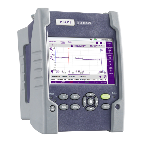
2000 PLATFORM OVERVIEW
5'' Touchscreen
1
2
Charge indicator
1
3
On indicator
4
File
5
Setup
6
Start/Stop
7
Testing indicator
2
3
4
5
6
7
8
On/Off
9
Home
Cancel
10
8
9
10
11
12
13
14
15
16
To access the User Manuals concerning the T-BERD/MTS-2000, go to the Home page and select
H
icon. Click on one link in the WebBrowser page to open the correponding manual in PDF. You
ELP
can also transfer pdf fi les onto USB key (see «Transferring fi les - Through USB key»).
Press Cancel to deactivate a function selected.
CONFIGURING A TEST IN SMART TEST - Configuration File
On the Home page, select Smart TEST icon.
In the Results page, press
1
2
Select the confi guration fi le corresponding to
4
your application and press Load as SMART
Press Load Confi g. to select the right
3
Confi g. key.
confi guration per your application and/or modify
the parameters.
summary of selected
confi guration
To create a confi guration fi le go in Expert mode (see «ExpertOTDR - Confi guring Test / Creating
Smart confi g. File».
PERFORMING A TEST IN SMART TEST MODE
Press
R
hard key to return to the
ESULTS
1
S
/S
results page and press
button.
TART
TOP
S
/S
TART
TOP
At the end of test, the results trace displays.
2
Trace: select the active trace (multi-traces analysis)
6
1
Event: move the active cursor onto events
Zoom: zoom on trace
2
Shift: displace the displayed trace section
Select Cursor A and/or B
3
Allows to modify some acquisition parameters
4
before lauching a new OTDR test in Smart TEST
mode
Save in a sor fi le and create a txt or pdf report of
5
the results
Switch to Fault Locator view
6
FDA21CFR§1040.10
CAUTION
LASER RAD IATION - DO NOT STARE
INTO BEAM
CLASS II LASER PRODUCT
SETUP
Confi gure the fi le storage
RESULTS
to return to Results page.
Direction keys & validation
11
12
Results
13
Loudspeaker
14
Mini USB port
15
AC/DC Input
16
Headset Jack
17
RJ45 connector
USB ports (2)
18
Power Meter port
19
VFL or Talkset port
20
17
18
19
20
S
hard key.
ETUP
S
ETUP
Step1: connector check
Step2: acquisition in progress
1
2
3
4
5
Advertisement
Table of Contents

Related Manuals for Viavi T-BERD/MTS-2000


Summary of Contents for Viavi T-BERD/MTS-2000
- Page 1 Viavi is not responsible for direct or indirect damage including damage to persons or property if the power supply is not use correctly. For assistance using one of the Viavi supplied adapt- ers (your specifi c regional adapter may not be available) please refer to the user manual.
- Page 2 Press «Exit» > «Remove USB» to correctly remove USB key from 2000 Platform (icon TECHNICAL ASSISTANCE If you require technical assistance, call 1-844-GO-VIAVI. For the latest TAC information, go to http:// www.viavisolutions.com/en/services-and-support/support/technical-assistance. T-BERD/MTS-2000 - Getting Started Manual - PN79000002202 Rev003 - November 2015 - Copyright © 2015...
Need help?
Do you have a question about the T-BERD/MTS-2000 and is the answer not in the manual?
Questions and answers