Table of Contents
Advertisement
Quick Links
Table of Contents
Introduction .................................................................................................... 2
Important Safety Information (Be Sure to Read) ........................................... 3
1. Overview ................................................................................................... 5
1.1 B1 Series .............................................................................................. 5
1.2 Front Panel ........................................................................................... 6
2. Installation ................................................................................................ 7
2.1 Placement ............................................................................................. 7
2.2 Back Panel ............................................................................................ 8
2.3 Connection ............................................................................................ 9
2.4 Recommended Cable Cross-section and Circuit Breakers (CBs) ............. 9
2.5 Battery Placement and Connections ..................................................... 10
2.6 Communication with PC ....................................................................... 12
2.7 User Outputs ....................................................................................... 12
3. Operation ................................................................................................ 13
3.1 Switching On ....................................................................................... 13
3.2 Switching Off ....................................................................................... 14
3.3 Operation Modes ................................................................................. 15
3.4 User Menu .......................................................................................... 16
3.5 Automatic Battery Test ......................................................................... 17
3.6 Overload ............................................................................................. 17
3.7 Audio Warnings ................................................................................... 18
3.8 Warnings Table ................................................................................... 18
4. Troubleshooting...................................................................................... 20
5. Maintenance ............................................................................................ 21
6. Technical Specifications ......................................................................... 22
Page | 1
B1 10kVA V1.0.1 -
Advertisement
Table of Contents

Related Manuals for Elen B1 Series

Summary of Contents for Elen B1 Series
-
Page 1: Table Of Contents
Table of Contents Introduction ....................2 Important Safety Information (Be Sure to Read) ........... 3 1. Overview ....................5 1.1 B1 Series ....................5 1.2 Front Panel ................... 6 2. Installation ....................7 2.1 Placement ..................... 7 2.2 Back Panel .................... 8 2.3 Connection .................... -
Page 2: Introduction
Company ……………………………… The B1 Series products are protected under a patent. Therefore, implementation of our proprietary technology by competitors is not permitted. Given the relevant standards and technology, device hardware configuration may be changed without notice. Technical specifications and dimension information are not binding unless formally confirmed by us Page | 2 –... -
Page 3: Important Safety Information (Be Sure To Read)
Important Safety Information (Be Sure To Read) Life Safety Use UPS in an access-restricted room (EN 62040-1-2). The UPS has its own power source (batteries). Therefore, there may be live power at the output even if the mains voltage is disconnected. ... - Page 4 Special Safety Information UPS’ electrical connections must be provided as shown in the manual. Be sure to check the compatibility of the UPS power to mains voltage and to total load that will be supplied with UPS. UPS must be stored in a dry environment between -10°C and 45°C temperature prior to commissioning.
-
Page 5: Overview
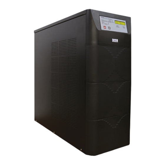
1. Overview 1.1. B1 Series UPS Cabin Dimensions UPS Power Width x Height x Depth (mm) (KW/KVA) 7/10 255 x 710 x 660 Backup Time Net Weight (kg) (min) (100% load/50% 10KVA load) 4/11 5/13 8/22 Figure 1.1 UPS Cabin Table 1.1 UPS Cabin Dimensions and Weights... -
Page 6: Front Panel
1.2. Front Panel Figure 1.3 Front Panel Mains voltages are within At least one of the mains voltages mains the tolerance limits. is not within the tolerance limits. UPS is operating in bypass UPS is not operating in bypass by-pass mode. -
Page 7: Installation
2. Installation 2.1. Placement UPS Placement Do not install the UPS on an uneven ground or in outdoors. Note that ventilation holes on side covers must not be clogged. Do not install the UPS in places with liquid ... -
Page 8: Back Panel
2.2. Back Panel Figure 2.3 Back Panel Part Function This ensures that ‘Low Battery’ and ‘Mains Failure’ warnings can be monitored from a User Outputs remote location by means of audible warning device or lamp. This ensures that the UPS can be monitored RS232 Port using a computer software. -
Page 9: Connection
2.3. Connection Figure 2.4 Connections Connections BATTERY (External Battery Middle (+) pole (-) pole Cabin) point INPUT Phase- Phase- Phase- Neutral Earth OUTPUT Phase- Neutral Earth Table 2.2 Terminals 2.4. Recommended Cable Cross-section and Circuit Breakers (CBs) UPS Power Cable Cross- Circuit Breaker (KW/KVA) section (mm²) -
Page 10: Battery Placement And Connections
The cables and the CBs must be replaced with the cables and the CBs of same type and capacities only. The CBs must be of time delay type. 2.5. Battery Placement and Connections UPS Cabin 30 pieces of 7-9AH (left side) (right side) Figure 2.5 30 pieces of 7-9AH Battery Placement and Connections... - Page 11 External Battery Cabin 30 pieces of 7-9AH (left side) (right side) Figure 2.7 30 pieces of 7-9AH Battery Placement and Connections 2x30 pieces of 7-9AH (left side) (right side) Figure 2.8 2x30 pieces of 7-9AH Battery Placement and Connections Page | 11 B1 10kVA V1.0.1 –...
-
Page 12: Communication With Pc
2.6. Communication with PC RS232 You can monitor the UPS over RS232 port using UPSilon2000 software that you will install on your computer (this is optional and therefore UPS software and RS232 cable must be ordered prior to use of this option). Using this software, you can monitor real- time UPS voltage and current information, battery information, malfunctioning warnings, etc. -
Page 13: Operation
3. Operation 3.1. Switching On Switch on the Input CB first and then the Battery CB (Figure 3.1). Press and hold the ON/OFF button until a warning beep sound, meanwhile observe the normal LED is on (Figure 3.2). Figure 3.1 Figure 3.2 If the mains voltages and the frequencies are within the limits, the mains and the by-pass LEDs will be on (Figure 3.3). -
Page 14: Switching Off
3.2. Switching Off If the UPS is in Normal Mode: Switch off your loads safely. Press the ON/OFF button briefly. Press the ON/OFF button briefly again to confirm bypass operation and observe the by-pass and the mains LEDs turn on (Figure 3.9, Figure 3.10). -
Page 15: Operation Modes
3.3 Operation Modes The B1 Series UPS has Online Double Conversion UPS and Three-Level Inverter technologies. Three-Level Inverter Technology ensures that UPS operates at high efficiency. The B1 Series UPS supports following operation modes. Figure 3.14 Bypass Mode Mains voltage is transferred to output via bypass line and over bypass/inverter unit. -
Page 16: User Menu
Figure 3.15 User will be responsible for any load malfunctions that may be experienced when switched to manual bypass mode without switching off the loads first. 3.4 User Menu 01-MAINS Instant information for mains voltages is displayed. 02-BYPASS Instant information for bypass voltage is displayed. 03-OUTPUT Instant information for output voltage and loading ratio is displayed. -
Page 17: Automatic Battery Test
07-WARNING The last 128 event log is recorded here. The date and the time of the events which are recorded in the log are not real-time. 08-PROGRAM NAME Firmware name is displayed. 3.5 Automatic Battery Test The UPS self diagnoses the batteries by running on battery automatically at every 30 days. -
Page 18: Audio Warnings
3.7 Audio Warnings Subject Alarm Warning Info 3 times consecutively at every 5 Battery Battery Battery sec. High Shutdown Fault Battery 2 times consecutively at every 2 Battery Test min. Load Over Load 3 times consecutively at every 5 Heat Over Heat Inv Over Heat Rec sec. - Page 19 Mains Low At least one of the mains voltages is below the lower limit. The UPS is started when the mains voltages and the frequencies are within the Mains Start limits. Normal Mode The UPS is in normal operation mode. Output S/C Short circuit at the loads, at the output, at the beam box or at the line.
-
Page 20: Troubleshooting
4. Troubleshooting Make sure you go through the table below before contacting the Technical Service. Cable connections and CB checks must be performed by authorized personnel only. Definition of Possible Cause Solution Failure ON/OFF button is pressed Press and hold ON/OFF button for at least UPS won’t to briefly. -
Page 21: Maintenance
5. Maintenance The UPS should only be opened by authorized personnel. The UPS must be completely off during maintenance. Mains and battery connections must be disconnected and batteries must be moved away from the UPS. Follow the ‘Important Safety Information’ and ‘Installation’ instructions during the maintenance. -
Page 22: Technical Specifications
Internal battery quantity Internal battery capacity (Ah) External battery cabinet Standard socket STANDARDS Safety EN 62040-1 EN 62040-2 UPS LIFETIME 10 years ELEN reserve the right of changing information in this without report. Page | 22 – B1 10kVA V1.0.1... - Page 23 AUTHORIZED TECHNICAL SERVICE Page | 23 B1 10kVA V1.0.1 –...
Need help?
Do you have a question about the B1 Series and is the answer not in the manual?
Questions and answers