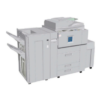
Ricoh B064 Service Manual
Hide thumbs
Also See for B064:
- Service manual (1465 pages) ,
- Service manual (1060 pages) ,
- Service manual (25 pages)
Advertisement
Quick Links
Advertisement

Summary of Contents for Ricoh B064
- Page 1 B064/B065/B140/B141/ B142/B143/B163/B228 SERVICE MANUAL 001360MIU RICOH GROUP COMPANIES...
- Page 3 ® ® RICOH GROUP COMPANIES...
- Page 5 B064/B065/B140/B141/ B142/B143/B163/B228 SERVICE MANUAL 001360MIU...
- Page 7 It is the reader's responsibility when discussing the information contained within this document to maintain a level of confidentiality that is in the best interest of Ricoh Corporation and its member companies. NO PART OF THIS DOCUMENT MAY BE REPRODUCED IN ANY FASHION AND DISTRIBUTED WITHOUT THE PRIOR PERMISSION OF RICOH CORPORATION.
- Page 9 Ricoh Corporation. Users of this manual should be either service trained or certified by successfully completing a Ricoh Technical Training Program. Untrained uncertified users utilizing...
-
Page 11: Documentation History
LEGEND PRODUCT CODE COMPANY GESTETNER LANIER RICOH SAVIN B064 6002 LD060 Aficio 1060 2560 B065 7502 LD075 Aficio 1075 2575 B140 DSm660 LD160 Aficio 2060 4060 B141 DSm675 LD175 Aficio 2075 4075 B142 DSm660 SP LD160 SP Aficio 2060 SP... - Page 13 1.1.3 MINIMUM SPACE REQUIREMENTS..........1-3 1.1.4 DIMENSIONS ...................1-4 B064 Series ..................1-4 B140 Series ..................1-5 1.1.5 POWER REQUIREMENTS ..............1-6 1.2 MAIN MACHINE (B064 SERIES/B140 SERIES)........1-7 1.2.1 ACCESSORY CHECK..............1-7 1.2.2 INSTALLATION PROCEDURE ............1-8 Removing Tapes and Retainers ............1-8 Connecting the ADF................1-10 Removing and Filling the Development Unit ........1-11 Re-installing the Development Unit.............1-13...
- Page 14 Removing Tapes and Retainers ............1-49 Installation...................1-49 1.10 KEY COUNTER BRACKET (B452) ............1-51 1.11 COPY CONNECTOR KIT..............1-52 1.11.1 COPY CONNECTOR KIT (B525-10, -12) FOR B064 SERIES ..1-52 ACCESSORY CHECK................1-53 Installation...................1-54 Installing the Hardware ...............1-55 1.12 COPY CONNECTOR KIT (B328-03) FOR B140 SERIES .....1-59 ACCESSORY CHECK................1-59...
- Page 15 1.16.2 INSTALLATION PROCEDURE ............1-84 Inserting DIMMs..................1-84 Installation Procedure .................1-85 1.16.3 PS3 (B525-08) ................1-87 1.16.4 USB 2.0 (B525-01) ...............1-88 ACCESSORY CHECK................1-88 Installation Procedure .................1-88 USB SP Settings.................1-89 1.16.5 IEEE1394 (G561) FIREWIRE INTERFACE........1-90 ACCESSORY CHECK................1-90 Installation Procedure .................1-91 UP Mode Settings for IEEE 1394............1-92 SP Mode Settings for IEEE 1394 ............1-93 1.16.6 IEEE802.11B WIRELESS LAN (G628).........1-94 ACCESSORY CHECK................1-94...
- Page 16 3.3.1 OPERATION PANEL................3-6 3.3.2 FRONT DOOR .................3-6 3.3.3 RIGHT COVERS ................3-7 3.3.4 LEFT COVERS.................3-8 3.3.5 REAR COVERS................3-9 3.4 SCANNER ....................3-10 3.4.1 ADF AND TOP COVERS ...............3-10 ADF.....................3-10 Top Covers ..................3-11 3.4.2 EXPOSURE GLASS...............3-12 3.4.3 SCANNER ORIGINAL SIZE SENSORS.........3-13 B064 Series/B140 Series...
- Page 17 3.4.4 LENS BLOCK .................3-14 3.4.5 EXPOSURE LAMP .................3-15 3.4.6 LAMP REGULATOR...............3-16 3.4.7 SCANNER MOTOR DRIVE BOARD (SDRB) .........3-17 3.4.8 SCANNER MOTOR................3-18 3.4.9 SCANNER HP SENSOR ..............3-19 3.4.10 SCANNER WIRE REPLACEMENT ..........3-20 Preparation for Removal ..............3-20 Wire Removal: Back ................3-21 Wire Removal: Front ................3-22 Attaching the New Wire ..............3-23 3.4.11 SCANNER HEATER..............3-25 3.5 LASER UNIT ...................3-26...
- Page 18 B140 Series ..................3-69 3.9.8 FUSING LAMPS, HOT ROLLER, AND PRESSURE ROLLER..3-70 B064 Series: Fusing Lamps..............3-70 B140 Series: Fusing Lamps..............3-71 Important Notes about Fusing Unit Assembly (B064 Series) ....3-76 3.9.9 PRESSURE ROLLER..............3-77 3.9.10 STRIPPER PAWLS ..............3-78 B064 Series ..................3-78 B140 Series ..................3-79 3.9.11 NIP BAND WIDTH ADJUSTMENT ..........3-80...
- Page 19 3.11.15 REGISTRATION AND BY-PASS UNIT REMOVAL ....3-112 3.12 PCBS AND HDD .................3-114 3.12.1 BCU BOARD (BASE ENGINE CONTROL UNIT) .......3-114 3.12.2 CONTROLLER BOARD .............3-115 B064 Series: Controller Board ............3-115 B140 Series: Controller Board ............3-116 3.12.3 IPU BOARD................3-117 B064 Series: IPU Board..............3-117 B140 Series: IPU, Mother Board............3-118...
- Page 20 SC500: Feed, Transport, Duplexing, and Fusing Systems ....4-21 SC600: Data Communication .............4-24 SC700: Peripherals................4-26 SC800: Overall System...............4-29 SC900: Miscellaneous ................4-32 4.2.3 ADDITIONAL SC CODES PRINTED IN SMC REPORT (B064 SERIES) ....................4-34 4.3 B140 SERIES SERVICE MODE..............4-36 4.3.1 SERVICE MODE LOCK/UNLOCK..........4-36 4.3.2 B140 SERIES SERVICE CALL CONDITIONS .......4-37 4.3.3 B140 SERIES SC CODE DESCRIPTIONS ........4-38...


Need help?
Do you have a question about the B064 and is the answer not in the manual?
Questions and answers