Table of Contents
Advertisement
Quick Links
Advertisement
Table of Contents

Related Manuals for Sonel SRM-0R1-4K1


Summary of Contents for Sonel SRM-0R1-4K1
- Page 3 USER MANUAL HIGH-CURRENT DECADE RESISTOR SRM-0R1-4k1 SONEL S.A. Wokulskiego 11 58-100 Świdnica Version 1.03 24.05.2021...
-
Page 4: Table Of Contents
8.1.6 Simulation of fault loop impedance ................10 Calibration of the device ......................11 10 Operation and maintenance ...................... 11 11 Transport............................ 12 11.1 Packaging ......................12 11.2 Transport conditions ....................12 12 Manufacturer ..........................12 SRM-0R1-4k1 – USER MANUAL... -
Page 5: Introduction
Then, connect the power cord to the appropriate connector on the back of the device. Operating the device without earthing is prohibited. After connecting SRM-0R1-4k1 to the mains, set the device in a manner that does not prevent its disconnection. Introduction This manual contains information about the design and operation of SRM-0R1-4k1 high-current decade resistor, including its operating limits and operational safety measures. -
Page 6: Intended Use
Intended use SRM-0R1-4k1 is a high-current decade resistor designed for simulation and inducing fault loop resistance using mains voltage of 220/380 V (230/400 V), 50 Hz AC. SRM-0R1-4k1 high-current decade resistor is used as a reference device for calibration and certification tests of measuring instruments included in MZC, MIE, MRP, MPI series and others according to the parameters of "phase-neutral", "phase-to-earth"... -
Page 7: Structure And Principle Of Operation
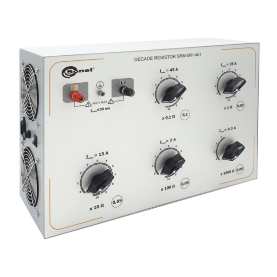
Fig. 3. SRM-0R1-4k1 consists of five decades connected in series. The first position is for the decade with lowest resistance values (Ω x 0.1), and the last for the decade with highest resistance values (x 1000 Ω). - Page 8 Fig. 1. Side panel of SRM-0R1-4k1 1 - fans 2 - switch of cooling system 3 - fuse (F 0.5 A) 3 – connector for the power cord Fig. 2. Connection diagram of decades in the device SRM-0R1-4k1 Tested measuring device Fig.
-
Page 9: Marking And Sealing
"0" as the power provided to resistor 2 Ω, in the second decade will exceed by 100% the permissible dissipation power. The algorithm of correct resistance setting for decades is presented in section 8.1. NOTE! Failure to follow the above set-up procedure may lead to excessive overheating of the device and its damage. SRM-0R1-4k1 – USER MANUAL... -
Page 10: Procedures For Adjusting The Resistance Of The Device
Rmax = 1 Ω + 10 Ω = 11 Ω Any other settings are not recommended, e.g. 3.2 Ω; 5.7 Ω etc. Position 10 Position 0 1 Ω Position 0 Position 0 Fig. 5. Connection diagram for adjusting the resistance of the second decade SRM-0R1-4k1 – USER MANUAL... -
Page 11: Adjusting The Third Decade
Rmax = 1 Ω + 10 Ω + 100 Ω + 1000 Ω = 1111 Ω Position 10 Position 9 Position 9 1 Ω 9 Ω Position 0 90 Ω Fig. 7. Connection diagram for adjusting the resistance of the fourth decade Any other settings are not recommended. SRM-0R1-4k1 – USER MANUAL... -
Page 12: Adjusting The Fifth Decade
When it is necessary to simulate the fault loop impedance in series using the device, activate an external calibration coil. Connection diagram of the measuring circuit is shown in Fig. 9. Tested measuring device SRM-0R1-4k1 Fig. 9. Simulation of fault loop impedance SRM-0R1-4k1 – USER MANUAL... -
Page 13: Calibration Of The Device
Before replacing the fuse, it is mandatory to disconnect the device from the power supply. The housing of SRM-0R1-4k1 may be cleaned with a soft, dry cloth. Do not use solvents or abrasive cleaners (powders, pastes, etc.). The electronic circuit of SRM-0R1-4k1 does not require cleaning, except for the sockets of test leads. -
Page 14: Transport
SONEL S.A. Wokulskiego 11 58-100 Świdnica Poland tel. +48 74 858 38 60 fax +48 74 858 38 09 E-mail: export@sonel.pl Web page: www.sonel.pl NOTE! Service repairs must be performed only by the manufacturer. Made in Russia. SRM-0R1-4k1 – USER MANUAL... - Page 16 SRM-0R1-4k1 – USER MANUAL...
Need help?
Do you have a question about the SRM-0R1-4K1 and is the answer not in the manual?
Questions and answers