Table of Contents
Advertisement
Quick Links
Advertisement
Table of Contents

Subscribe to Our Youtube Channel
Related Manuals for Sonel DB-1


Summary of Contents for Sonel DB-1
- Page 3 USER MANUAL DEMONSTRATION BOARD DB-1 SONEL S. A. Wokulskiego 11 58-100 Świdnica Poland Version 2.00 27.05.2022...
- Page 4 DB-1 – USER MANUAL...
-
Page 5: Table Of Contents
Insulation resistance measurements in the L-PE circuits ..........21 5 Replacement of fuses ..................21 6 Cleaning and maintenance ................22 7 Dismantling and disposal ................22 8 Technical specifications ................22 9 Standard accessories ..................22 10 Manufacturer ....................23 DB-1 – USER MANUAL... -
Page 6: Safety
Safety The DB-1 demonstration board has been designed for the purpose of simulation of measurements, whose results determine the safety conditions of a virtual installation. Therefore, in order to guarantee ap- propriate operation and correctness of the obtained results, the following recommendations must be fol- lowed: ... -
Page 7: Application
Application The DB-1 demonstration board is an indispensable element of training courses regarding reali- sation of electric measurements. It may be applied in schools, distribution centres of meters used in the power industry as well as in training centres. The board may be used for the purpose of simulation of the following measurements: ... -
Page 8: The Front Panel
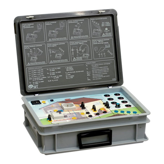
The front panel Arrangement of sockets and switches Fig. 1. Arrangements of the panel elements of the DB-1 demonstration board Power supply network socket 230 V Additional PE socket 230 V power supply signalling diode RCD switch Measurement socket TN network jumper... -
Page 9: Position Of Switches
– high short circuit loop impedance. Z – the activation current of the RCD is lower than the required value (damaged RCD or ex- RCD-I ≈ 15 mA cessive leakage current of the installation). The leakage current of the installation I DB-1 – USER MANUAL... -
Page 10: Measurements
(simulation of irregularities). In order to do so, before you proceed to switch in the „red” position. Having finished the measurement, perform the measurement place the Z switch again in the „green” position. place the Z DB-1 – USER MANUAL... - Page 11 „red” for the TT network (TT jumper): Z of the network + 10 Ω Switch Z L-PE of the network – the network impedance in the L-N circuit of the socket to which the demonstra- tion board cable is connected. DB-1 – USER MANUAL...
-
Page 12: Measurement Of The Short Circuit Loop Impedance In The L-N Circuit
„red” for the TT network (TT jumper): Z of the network + 5.5 Ω Switch Z of the network – the network impedance in the L-N circuit of the socket to which the demonstra- tion board cable is connected. DB-1 – USER MANUAL... -
Page 13: Measurement Of The Parameters Of The Rcd Switch
25 V. Should the acceptable touch voltage U during measurement be set at 50V, the meter will perform the measurements and display the results. DB-1 – USER MANUAL... - Page 14 The RCD switch-I activated during the measurement” „red” for the TN and TT network : I = 15…. 30 mA, T ≈ 31 V, Switch U < 300 ms, U ≈ 1 kΩ or „excessive U voltage” DB-1 – USER MANUAL...
-
Page 15: Measurements Of The Earth Resistance
The parameters of the pulse are defined by two values: the duration of the pulse leading edge t and the duration of the semi-peak t The DB-1 demonstration board permits to perform measurements of the earth resistance of three distinct earth electrodes, namely R . Earth resistance measurement R is also pos- sible using the clamp method. -
Page 16: Measurement Of The Earth Electrode Resistance Using Meters Of The Mru Series
(MRU-XXX) to the sockets in accord- ance with Figure 8, perform the measurement. Fig. 8. Connection of the meter Expected results = 4.7 Ω = 200 Ω = 200 Ω DB-1 – USER MANUAL... -
Page 17: Earth Resistance Measurement R By Means Of The Technical Method
(MRU-XXX) to the sockets in accord- ance with Figure 10, Fig. 10. Connection of the meter perform the measurement. Expected results = 6.8 Ω = 200 Ω = 200 Ω DB-1 – USER MANUAL... -
Page 18: Earth Resistance Measurement R By Means Of The Two-Clamp Method
the measurement may provoke activation of the RCD switch (it is impossible to perform a Fig. 12. Connection of the meter measurement). Expected results = 100 Ω + Z of the network DB-1 – USER MANUAL... -
Page 19: Earth Resistance Measurement R
the measurement may provoke acti- Fig. 14. Connection of the meter vation of the RCD switch (it is impos- sible to perform a measurement). Expected results = 6.8 Ω + Z of the network DB-1 – USER MANUAL... -
Page 20: Earth Resistivity Measurements
Fig. 15. Connection of the meter Expected results Switch in the position 5 m: ρ = 31 Ωm Switch in the position 10 m: ρ = 295 Ωm Switch in the position 20 m: ρ = 5.9 kΩm DB-1 – USER MANUAL... -
Page 21: Measurements Of The Continuity Of Equipotential Bondings
connect the meter with cables to the network socket of the board in accordance with Figure 17, perform the measurement. Expected results Fig. 17. Connection of the meter (P1-P3) = 0.4 Ω cont DB-1 – USER MANUAL... -
Page 22: Insulation Resistance Measurement
Before the measurements are performed, make sure the measured object is disconnected from the power supply network. This is why the meters manufactured by SONEL S.A. are equipped with a voltmeter. -
Page 23: Insulation Resistance Measurements In The L-Pe Circuits
Solely the following fuse elements are approved for the demonstration board: F4A 250 V or T3,15 250 V. In the case fuse elements which are not specified in the present manual are used, there is a risk of damage to the device and a serious danger for the user. DB-1 – USER MANUAL... -
Page 24: Cleaning And Maintenance
The standard set of equipment supplied by the manufacturer includes: test lead 0.7 m, black (banana plugs) – WAPRZ0X7BLBB, mains cable with IEC C13 plug – WAPRZ1X8BLIEC, 4x configuration jumper – WAPOZZW1, user manual, declaration of verification. DB-1 – USER MANUAL... -
Page 25: Manufacturer
The manufacturer and provider of warranty and post-warranty service: SONEL S.A. Wokulskiego 11 58-100 Świdnica Poland tel. +48 74 858 38 60 fax +48 74 858 38 09 E-mail: export@sonel.pl Web page: www.sonel.pl NOTE! Service repairs must be performed only by the manufacturer. DB-1 – USER MANUAL... - Page 26 NOTES DB-1 – USER MANUAL...
Need help?
Do you have a question about the DB-1 and is the answer not in the manual?
Questions and answers