
Related Manuals for Murr Elektronik DataPanel xtreme DB DP-34044-3


Summary of Contents for Murr Elektronik DataPanel xtreme DB DP-34044-3
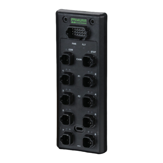
- Page 1 A Murrelektronik Company A Murrelektronik Company xtreme DB DP-34044-3 User Guide...
-
Page 2: Table Of Contents
| CONTENTS 1. Concerning this manual 2. Safety Information 2.1 Designated Use 2.2 Target Groups 2.3 Regulations 2.3.1 General Information 2.4 License Disclaimer 2.5 Example of Symbols 2.5.1 Use of Attention Signs 2.5.2 Use of Danger Signs 3. Installation Information 3.1 XtremeDB Installation 4. -
Page 3: Concerning This Manual
A Murrelektronik Company 1. CONCERNING THIS MANUAL The text, illustrations, diagrams and examples used in this manual exist solely for the purpose of explaning the operation and usage of xtremeDB Input/Output modules. If you have any further questions regarding the installation and set-up of the equipment de- scribed in this manual, please do not hesitate to contact us. We will be glad to assist you. Murrelektronik reserves the right to make technical changes or modifications to this manual without prior notice. 2. SAFETY INFORMATION 2.1 DESIGNATED USE The input/output modules of the XtremeDB series are designated for use only in those areas as described in this manual. Strict adherence to the data specified in this manual must be ensured. The products have been developed, manufactured, tested and documented in compliance with currently valid safety codes. The equipment poses no danger to operating personnel or material if configuration, assembly and operation are performed in compliance with the stated handling and safety regulations. Unqualified intervention in the hardware and software of our equipment, disregard of warning labels found on the equipment or non-observance of the information in this manual can result in injury or serious damage to man and/or material. Any application or usage beyond and above this shall be regarded as non-designated. Warning! Good chemical and oil resistance. When using aggressive mediums, material resistance based on application must be checked. 2.2 TARGET GROUPS This manual addresses itself exclusively to qualified and trained electricians knowledgeable in the safety standards of automation technology. Only a qualified, trained electrical tradesman knowledgeable in the safety standards of mobile industry may perform... -
Page 4: Example Of Symbols
vision of this End User License, even in the event of the fault, tort (including negligence), strict liability, breach of contract or breach of warranty of Murrelektronik, or any supplier, and even if Murrelektronik or any supplier has been advised of the possibility of such damages. 2.5 EXAMPLE OF SYMBOLS 2.5.1 USE OF ATTENTION SIGNS Notes containing important information are specially marked. These are illustrated as follows: Attention text... 2.5.2 USE OF DANGER SIGNS Danger signs are indicated by text and a corresponding symbol inside of a frame CAUTION! Disregard of safety measures may result in damage to equipment and other serious consequences. 3. - Page 5 A Murrelektronik Company 1.3” ATTENTION! Modules must be mounted a minimum of 3mm from each other.
-
Page 6: Module Overview
4. MODULE OVERVIEW Configuration & Power Plug CAN Ports 1 & 2 Non-Isolated 16 Outputs... -
Page 7: Configuring The Baud Rate
A Murrelektronik Company 4.1 CONFIGURING THE BAUD RATE Configuration of the baud rate is done using pins 1 & 7 of the Power and Configuration plug shown below. Currently there are 2 baud rates supported, 250kb and 500kb. If you are connecting to a 250kb network no jumpers are required. If connecting to a 500kb network, jumper pin 1 to pin 7. Configuration & Power Plug Baud1-A Baud1-B 9 10 11 12 13 14 15 16 17 18 Baud Rate No Jumper = 250kb Baud1-A to Baud1-B = 500kb Please note that all devices on the same J1939 network must have the same baud rate All unused pins need to be plugged with a Deutsch #114017 sealing plug to maintain the IP67 rating... -
Page 8: Configuring The Node Id
4.2 CONFIGURING THE NODE ID The Node ID is configured by jumpering the matching Config-A to Config-B. The Node ID starts with a base source address of 224 0xE0 and PGN of 61408 (0xEFE0) with no jumpers installed. The offset address is configured with the use of binary coded decimal (BCD). A power cycle is required when changing the Node ID. If a duplicate source address is on the network on power up our module will stay in address arbitration mode and will not function. Config4-A Config3-A Config2-A Config1-A Node ID (0-15 Offset) in BCD Config1-A (pin 2) to Config1-B (pin 8) = 1’s Config2-A (pin 3) to Config2-B (pin 9) = 2’s 9 10 11 12 Config3-A (pin 4) to Config3-B (pin 10) = 4’s Config4-A (pin 5) to Config4-B (pin 11) = 8’s 13 14 15 16 17 18 Config1-B Config2-B Config3-B... -
Page 9: Powering The Module
A Murrelektronik Company 4.3 POWERING THE MODULE The module recieves its power from the CAN ports. The module power is limited to 13 amps and is used to power connected modules down the line. This power is also used for all input ports as well. CAN Ports 1 & 2 Non-Isolated Power (J1939) (Module & Input-13A) Pin 2 = CAN High Pin 1 = 8-32V DC Pin 4 = CAN Low Pin 3 = Ground A The connection between CAN1 & CAN2 for the power feed is not fused (protected from short circuit current). During installation the module power wiring on CAN1 &... -
Page 10: Leds
4.4 LEDs During start up the LEDs will come on for 3-5 seconds to verify that they are working (bulb test). PWR LED - Blue Indicates module power is connected FLT LED - Red Fault Status COM LED - Green Communication Status STAT LED - Green Module Status Buss Power - Blue P1 = Power for ports 1 & 2 P2 = Power for ports 3 & 4 P3 = Power for ports 5 & 6 P4 = Power for ports 7 & 8 PORT I/O LED - Yellow Left LED = Output A Right LED = Output B... -
Page 11: Led Status
A Murrelektronik Company 4.4.1 LED STATUS COM LED - Green Communication Status COM Fault Description Bootload Mode Indicates traffic on bus Valid Communication Network Source Address (SA) Arbitration 1 Short CANBUS Hardware Fault 2 Short 1 Long Output Control Message Missing 3 Short DM13 Detected* 4 Short * See J1939-73 diagnostics, another device has requested module to stop broadcasting FLT LED - Red Fault Status Fault Description Bootload Mode 1 Short 1 Short Output Over Current Fault 1 Short Low Voltage Warning 2 Short... -
Page 12: Circuit Protection
4.5 CIRCUIT PROTECTION Buss Power The module shall monitor Power Buss Bank current and shut off all bank outputs if the maximum current exceeds 13 amps per buss. Both short circuit and overcurrent protection is provided. P1 = Ports 1 & 2 power, 13 amps. P2 = Ports 3 & 4 power, 13 amps. P3 = Ports 5 & 6 power, 13 amps. P4 = Ports 7 & 8 power, 13 amps. Module Power The module power delivered by the CAN ports has both short circuit and overcurrent protection. This circuit has a separate ground that is supplied by the CAN port as well, Ground (A) Output Power This module has both 10 amp and 4 amp outputs. The outputs have both short circuit and overcurrent protection. (See Figure 1) (2) 10A (14) 4A Reseting an output fault will require cycling of the module power unless the Controller Mode Output Reset is enabled. If the Control- ler Mode Output Reset is enabled the fault will be reset if the output is turned off, limit of 5 times before a cycle of module power will be required. An output fault will not effect other outputs on the module. Figure 1 Output Over Current Curve Amps Seconds... -
Page 13: Module Configuration
A Murrelektronik Company 5. MODULE CONFIGURATION 5.1 CONFIGURATION STEPS Module default configuration: • Factory Default Config returns 1 in Status message 1-Status 1, this should not be on if the module has been configured. • Default operation of the module is on/off digital control. PWM control messages are not needed. • Default configuration does not require a Command 0x52 message to enable operation. Command 0x52 (This message needs to be sent until the message confirmation bit is set true): Name Data Type Byte Bits Description Command Byte Command for index pointer (which message your sending) Enables Controller Mode Output Reset. Enabled (01) = cycling the output will reset the fault, Ctrl Mode Reset 2 bit... - Page 14 Status messages - Status message 1 PGN (EF(Controller Source Address)): • Status 1 – Factory default configuration returns a value of 1, this should not be on if a module has been configured. • Status 2 – Configuration Saved returns a value of 1 if the alternate configuration was on (value of 1) and saved the configuration using “Save Configuration” in Command 52. • Status 3 – Alternate configuration, a new configuration was made to the module but hasn’t been saved. • Status 7, 9-13 – Returns a value of 1 each time a Command message 52-58 is sent, to ensure each configuration has been sent. This is on for a brief moment and then resets. Command 0x51(Outputs digital control and Inputs power control) and PWM control messages need to be consistently sent. Please note PGNs are changing based on Node ID (node address), see section “PGNs USED” for details. Configuration Sample Flowchart: Configure Module (Command 0 x 52)
-
Page 15: Output Configuration
A Murrelektronik Company 5.2 OUTPUT CONFIGURATION 5.2.1 POWERING THE OUTPUTS Configuration & Power Plug Power 4 9 10 11 12 Ground(B) 13 14 15 16 17 18 Power 1 Ground(B) Power 2 Ground(B) Power 3 Ground(B) Power (Output only) Power 1 = 13 amps for ports 1 & 2 (Outputs 1A, 1B, 2A, 2B) Power 2 = 13 amps for ports 3 & 4 (Outputs 3A, 3B, 4A, 4B) Power 3 = 13 amps for ports 5 & 6 (Outputs 5A, 5B, 6A, 6B) Power 4 = 13 amps for ports 7 & 8 (Outputs 7A, 7B, 8A, 8B) -
Page 16: Output Layout
5.2.2 OUTPUT LAYOUT Ground(B) Output B (4A) Output A (10A) Ground(B) Power Outputs Pin 1 = Ground (B) • Port 1, Pin 4: Output 1A Pin 3 = Ground (B) • Port 1, Pin 2: Output 1B Configurations • Port 2, Pin 4: Output 2A Ports 1-8: • Port 2, Pin 2: Output 2B 1. Digital high side 2. PWM • Port 3, Pin 4: Output 3A • Port 3, Pin 2: Output 3B Amperage • Port 4, Pin 4: Output 4A Output 1A & 3A are 10A • Port 4, Pin 2: Output 4B All other outputs = 4A • Port 5, Pin 4: Output 5A • Port 5, Pin 2: Output 5B • Port 6, Pin 4: Output 6A • Port 6, Pin 2: Output 6B • Port 7, Pin 4: Output 7A • Port 7, Pin 2: Output 7B • Port 8, Pin 4: Output 8A • Port 8, Pin 2: Output 8B All Ground (B) connections must be made in order to achieve the total specified current. -
Page 17: Configuring Outputs
A Murrelektronik Company 5.2.3 CONFIGURING OUTPUTS Output Mode There are two ways to configure the outputs. All configuration is done through the same PGN. PGN 61408 is used for multiple messages by use of a different value put into the “command” byte of the PGN. This value is used a an index or pointer as to where the information goes in the module. 1. All Output Configuration (only used if you want all the outputs to be configured the same) Configuring all of the outputs is done through the “MODE1” byte in PGN 61408. The J1939 message structure, Command Value 61408 (0xEFE0) 82 (0x52) Source Address Transmit rate (0x?? (CSA*)) 50 ms PDU Format Msg timeout 239 (0xEF) 200 ms PDU Specific Priority 224 (0xE0) Built Message (0x18EFE0??) Name Data Type... - Page 18 2. Individual Configuration Individual output configuration is done through the “output mode” nibble in PGN 61408 Command Value 61408 (0xEFE0) 83 (0x53) Source Address Transmit rate (0x?? (CSA*)) 50 ms PDU Format Msg timeout 239 (0xEF) 200 ms PDU Specific Priority 224 (0xE0) Built Message (0x18EFE0??) Name Data Type Byte Bits Description Command Byte Command for index pointer (which message your sending) Mode 1A 1,2,3,4 Mode 1B 5,6,7,8 Mode 2A...
- Page 19 A Murrelektronik Company 4. High Current Output Configuration Command Value 88 (0x58) 61408 (0xEFE0) Source Address Transmit rate 50 ms (0x?? (CSA*)) PDU Format Msg timeout 239 (0xEF) 200 ms PDU Specific Priority 224 (0xE0) Built Message (0x18EFE0??) Name Data Type Byte Bits Description Command Command for index pointer Port 1A Output 1A (0-100) Set amp range 0.0-10.0A = Data Range 0-100...
-
Page 20: Output Operation
5.2.4 OUTPUT OPERATION The output operation will be different depending on the configuration chosen for the output. 1. Disabled, MODE = 0 It is recommended to disable any outputs that aren’t being used. Putting a “0” in the mode for an output disables the output and prevents it from being turned on. 2. On/Off, MODE = 1 (Used for Discrete Operation) This puts the output into the standard discrete operation mode. The use of bit pairs in Control Message 1 of PGN 61408 will turn the output on or off. High Bit Low Bit 3. Data, MODE = 2 (Used for PWM Control using a value of 0-4000) This puts the output into PWM control with a value of 0 - 4000 equaling 0 - 100% of the duty cycle. Two bytes are allocated for each of the PWM control messages with the first 12 bits being used for the value. The first byte and the first 4 bits of the second byte are put together for 12 bit control of the output. - Page 21 A Murrelektronik Company B. Amperage Feedback Status Message 4 (Ouput Amperage Feedback OUT 1A-4B) Name Data Type Byte Bits Description OUT 1A AMP FEEDBACK Current reading on Output 1A, 100mA/bit OUT 1B AMP FEEDBACK Current reading on Output 1B, 100mA/bit OUT 2A AMP FEEDBACK Current reading on Output 2A, 100mA/bit OUT 2B AMP FEEDBACK Current reading on Output 2B, 100mA/bit Byte OUT 3A AMP FEEDBACK Current reading on Output 3A, 100mA/bit OUT 3B AMP FEEDBACK Current reading on Output 3B, 100mA/bit OUT 4A AMP FEEDBACK Current reading on Output 4A, 100mA/bit OUT 4B AMP FEEDBACK Current reading on Output 4B, 100mA/bit Status Message 5 (Ouput Amperage Feedback OUT 5A-8B) Name Data Type Byte...
-
Page 22: Status Messages
5.3 STATUS MESSAGES 5.3.1 MODULE STATUS Status Message 1 (Software and Node Status) Name Data Type Byte Bits Description (0xEF(CSA))* Software Version Version of the current software Byte Software Revision Revision of the current software Status 1 Factory Default Configuration Status 2 Configuration Saved (module is configured) Status 3 Alternate Configuration Received Status 4 Node Alive 2 Bit Status 5 Node Fault Present Status 6 Fault Count not Zero... - Page 23 A Murrelektronik Company Status Message 2 (Configuration and Output Status) Name Data Type Byte Bits Description 65531 (0xFFFB) Config Pair 1 Baud rate configuration jumper is applied Config Pair 2 Node ID 1's configuration jumper is applied Config Pair 3 Node ID 2's configuration jumper is applied Config Pair 4 Node ID 3's configuration jumper is applied Config Pair 5 Node ID 4's configuration jumper is applied Output 1A Status Status of Output 1A, (00 = off), (01 = on), (10 = fault) Output 1B Status Status of Output 1B, (00 = off), (01 = on), (10 = fault) Output 2A Status Status of Output 2A, (00 = off), (01 = on), (10 = fault) Output 2B Status Status of Output 2B, (00 = off), (01 = on), (10 = fault) Output 3A Status Status of Output 3A, (00 = off), (01 = on), (10 = fault)
-
Page 24: Data Sheet
5.4 DATA SHEET 5.4.1 PORT CONFIGURATION Configuration & Power Plug See reverse for pinout guide 9 10 11 12 13 14 15 16 17 18 CAN Ports 1 & 2 Non-Isolated Power (J1939) (Module & Input-13A) Pin 2 = CAN High Pin 1 = 8-32V DC Pin 4 = CAN Low Pin 3 = Ground A Output Ports Power Outputs Pin 1 = Ground B • Port 1, Pin 4: Output 1A Pin 3 = Ground B • Port 1, Pin 2: Output 1B Configurations • Port 2, Pin 4: Output 2A Ports 1-8: • Port 2, Pin 2: Output 2B 1. Digital high side... -
Page 25: Technical Data
A Murrelektronik Company Configuration & Power Plug Pinouts Jumper from A to B to configure Power (Output Only) Baud Rate 13. Power 1 = 13A for ports 1 & 2 (Outputs 1A, 1B, 2A, 2B) No Jumper = 250kb 14. Power 2 = 13A for ports 3 & 4 (Outputs 3A, 3B, 4A, 4B) 1. Baud1-A Baud1-A to Baud1-B = 500kb 15. Power 3 = 13A for ports 5 & 6 (Outputs 5A, 5B, 6A, 6B) 7. Baud1-B 6. Power 4 = 13A for ports 7 & 8 (Outputs 7A, 7B, 8A, 8B) Node ID (0-15) 16. Ground 1B = for ports 1 & 2 (Outputs 1A, 1B, 2A, 2B) 2. Config1-A = 1s 17. Ground 2B = for ports 3 & 4 (Outputs 3A, 3B, 4A, 4B) 8. Config1-B 9 10 11 12 18. Ground 3B = for ports 5 & 6 (Outputs 5A, 5B, 6A, 6B) 12. Ground 4B = for ports 7 & 8 (Outputs 7A, 7B, 8A, 8B) 3. Config2-A 13 14 15 16 17 18 = 2s 9. Config2-B 4. Config3-A = 4s... -
Page 26: Message Structure
6. MESSAGE STRUCTURE All PGNs are shown as module configured with no jumpers (Offset = 0) Value 61408 (0xEFE0) Node offset of 0 82 (0x52) Source Address Transmit rate (0x?? (CSA*)) 50 ms PDU Format Msg timeout 239 (0xEF) 200 ms PDU Specific Priority 224 (0xE0) Built Message (0x18EFE0??) *CSA = Controller Source Address... - Page 27 A Murrelektronik Company J1939 Output Control - Control Message 1 (Output Control) Command Value 81 (0x51) Name Data Type Byte Bits Description Command Byte Command for index pointer (which message you’re sending) Output1A Output1B Output2A Output2B Output3A Output3B Output4A Output4B 2 bit Turns the output on when in "On/Off" Mode, (not used when using any other mode) Output5A Output5B Output6A Output6B Output7A Output7B Output8A Output8B Byte J1939 Output Configuration 2 Command Value 83 (0x53) Name Data Type Byte...
- Page 28 All PGNs are shown as module configured with no jumpers (Offset = 0) 61408 (0xEFE0) Node offset of 0 Source Address Transmit rate (0x?? (CSA*)) 50 ms PDU Format Msg timeout 239 (0xEF) 200 ms PDU Specific Priority 224 (0xE0) Built Message (0x18EFE0??) J1939 Output Configuration 3 Command Value Name Data Type Byte...
- Page 29 A Murrelektronik Company Control Message 2 (PWM1) 65308 (0xFF1C) Node offset of 0 Transmit rate Source Address (0x?? (CSA*)) 50 ms Msg timeout PDU Format 255 (0xFF) 200 ms PDU Specific Priority 28 (0x1C) Built Message (0x12FF1C??) Name Data Type Byte Bits Description PWM Ctrl Output 1A Byte Not Used Byte Not Used PWM Ctrl Output 1B 12 Bit PWM Output 1B, Byte 1 (12 bit, uses the 1st byte and the first 4 bits of the 2nd byte)
- Page 30 Control Message 4 (PWM3) 65310 (0xFF1E) Node offset of 0 Source Address Transmit rate (0x?? (CSA*)) 50 ms PDU Format Msg timeout 255 (0xFF) 200 ms Priority PDU Specific 30 (0x1E) Built Message (0x12FF1E??) Name Data Type Byte Bits Description PWM Ctrl Output 5A 12 Bit PWM Output 5A, Byte 1 (12 bit, uses the 1st byte and the first 4 bits of the 2nd byte) 1, 2, 3, 4 PWM Ctrl Output 5B 12 Bit PWM Output 5B, Byte 1 (12 bit, uses the 1st byte and the first 4 bits of the 2nd byte) 1, 2, 3, 4 PWM Ctrl Output 6A...
- Page 31 A Murrelektronik Company Status Message 1 (Software and Node Status) (0xEF(CSA)) Source Address Transmit rate 224 (0xE0) Node offset of 0 50 ms PDU Format Msg timeout 239 (0xEF) 200 ms PDU Specific Priority (0x??(CSA)) Built Message (0x18EF??E0) Name Data Type Byte Bits Description Software Version Version of the current software Byte Software Revision Revision of the current software Status 1 Factory Default Configuration Status 2...
- Page 32 All source addresses are shown as module configured with no jumpers (Offset = 0) Status Message 2 (Configuration and Output Status) 65531 (0xFFFB) Source Address Transmit rate 224 (0xE0) Node offset of 0 50 ms PDU Format Msg timeout 255 (0xFF) 200 ms PDU Specific Priority 251 (0xFB) Built Message (0x18FFFBE0) Name Data Type Byte...
- Page 33 A Murrelektronik Company Status Message 3 (Controller Information) 65532 (0xFFFC) Source Address Transmit rate 50 ms 224 (0xE0) Node offset of 0 PDU Format Msg timeout 255 (0xFF) 200 ms PDU Specific Priority 252 (0xFC) Built Message (0x18FFFCE0) Name Data Type Byte Bits Description CNFG1 Hardware Configuration Byte CNFG2 PCB Assembly Revision VBAT 10 Bit Battery Voltage...
- Page 34 All addresses are shown as module configured with no jumpers (Offset = 0) Status Message 5 (Output Amperage Feedback Port 5 -8) PGN 5 65524 (0xFFF4) Source Address Transmit rate 224 (0xE0) Node offset of 0 50 ms PDU Format Msg timeout 255 (0xFF) 200 ms PDU Specific Priority 243 (0xF4) Built Message (0x18FFF4E0) Name Data Type...
-
Page 35: Pgns Used
A Murrelektronik Company 7. PGNs USED Depending on the Node ID selected for the module, the PGNs and source address will be different for the module. The section below shows which are used for each Node ID. Module Node ID Control* PWM1* PWM2* PWM3* PWM4* Output Status Analog Status Amp Data 1-4 Amp Data 5-8 Fault Count Status (EF(CSA)) EFE0 FF1C FF1D FF1E FF1F FFFB (SA=E0) FFFC (SA=E0) FFF3 (SA=E0) FFF4 (SA=E0) FFE6 (SA=E0) (SA=E0) (EF(CSA)) EFE1... -
Page 36: Firmware Updates
8. FIRMWARE UPDATES All modules are capable of in the field firmware updates with the use of the xtreme DB Programming Kit (DP-34005-12). DP Loader is the software used to download the firmware to the xtreme DB blocks. Please reference the DP Loader User Manual for instructions. - Page 37 A Murrelektronik Company A Murrelektronik Company 1327 Northbrook Parkway, Suite 460 | Suwanee, GA 30024 P: 770-497-9292 | F: 770-497-9391 | murrinc.com...
Need help?
Do you have a question about the DataPanel xtreme DB DP-34044-3 and is the answer not in the manual?
Questions and answers