
Related Manuals for Murr Elektronik MIRO GSM


Summary of Contents for Murr Elektronik MIRO GSM
- Page 1 Manual MIRO GSM Safety Description Installation Software Run Mode Configuration Remote Access Technical Data Accessories www.comoso.com...
-
Page 2: Publisher's Note
Manual MIRO GSM Publisher's Note User Manual for MIRO GSM DI6 DO4R 24 VDC Art. No. 52530 MIRO GSM ADI6 DO4R 24 VDC Art. No. 52531 MIRO GSM DI6 DO4R 230 VAC Art. No. 52532 Version 1.3 Edition 11_11 EN... -
Page 3: Service And Support
Manual MIRO GSM Service and Support Website: www.murrelektronik.com In addition, our Customer Service Center (CSC) will be glad to assist you: The CSC supports customers over the entire course of the project, during planning and the conception of customer applications, configuration, installation, and start-up. We also offer competent consulting or –... -
Page 4: Table Of Contents
1.2 Qualified Personnel ........................8 1.3 Safety Instructions ......................... 9 2. Description ............................11 2.1 Short Description of the MIRO GSM ................... 11 2.2 Application Examples ........................12 2.3 Short Instructions ......................... 12 3. Installation / Scope of Supply ......................15 3.1 Selecting the Antenna ........................ - Page 5 6.4 Input Configuration ........................31 6.4.1 General Information ......................31 6.4.2 Digital Inputs (MIRO GSM DI6 DO4R 24 VDC, Art. No. 52530 and MIRO GSM DI6 DO4R 230 VAC, Art. No. 52532) ......................31 6.4.3 Parallel Message Handling ....................32 6.4.4 Time-delayed Messages on Signal Reception ..............
-
Page 6: Important Information
Manual MIRO GSM Important Information Important instructions in this Manual are indicated by the use of colors and are marked accordingly. DANGER Immediate danger Failure to observe this warning will immediately result in death or severe personal injury. WARNING Possible danger Failure to observe this warning may possibly result in death or severe personal injury. -
Page 7: Safety
Manual MIRO GSM 1. Safety 1.1 Intended Purpose The products that are described in this manual were developed, manufactured, tested, and documented in compliance with the relevant safety standards. In normal cases, these products do not constitute any danger to persons or objects, provided the handling specifications and safety instructions described in this manual are observed. -
Page 8: Safety Instructions
Manual MIRO GSM The requirements concerning qualified personnel are dependent on the requirements profiles described in ZVEI and VDMA publication Only electricians who know the contents of this manual may install and maintain the products described here. "Weiterbildung in der Automatisierungstechnik“(Further training in automation systems), published by ZVEI and VDMA in the Maschinenbau-Verlag, P.O.Box 710864 in D-60498... - Page 9 Do not allow a voltage exceeding 240 VAC to access the device itself. Only fit or remove the MIRO GSM when it is in deenergized state. Comply with the regulations and customary standards when you perform the electrical installation of the device.
-
Page 10: Description
The password option prevents unauthorized remote access to MIRO GSM by third parties. MIRO GSM sends out a message at regular intervals automatically, for example, the MIRO GSM sends out a message in case of power loss. When power is restored, the MIRO GSM announces its operational state again with a new message. -
Page 11: Application Examples
1. Snap the MIRO GSM on to the mounting rail. 2. Hook up the MIRO GSM as described in the connection diagrams on pages 16 to 16. 3. Open the front cover and insert the SIM card. - Page 12 The MIRO GSM then starts its initialization routine. 5. Caution: Do not access the MIRO GSM. 6. Load the MIRO GSM Configuration Software (Service and Start-up Kit Art. No. 52535, or download from www.murrelektronik.com). 7. Connect the RS232 interface of your PC or notebook to the programming interface of the MIRO GSM.
- Page 13 Windows in the Control Panel under System / Hardware / Connections. 13. Download the file to MIRO GSM. 14. Wait approx. 100 s until the MIRO GSM is ready, i.e. the state and GSM LEDs flash at a rate of 3 seconds.
-
Page 14: Installation / Scope Of Supply
Check the strength of the transmitted signal from the selected provider before ordering the antenna. The MIRO GSM is supplied without antenna. In the switch cabinet, the MIRO GSM Outdoor Antenna Art.No. 52534 provides much better results than the stub antenna Art. No. 52533. -
Page 15: Connecting The Inputs
240 VAC may not be applied to the device. CAUTION Only fit or remove the MIRO GSM when it is in deenergized state. The MIRO GSM is isolation-protected and does not require grounding. Connect the MIRO GSM according to the schematic diagram below. -
Page 16: Test And Reset Buttons
Manual MIRO GSM 3.3 TEST and RESET Buttons TEST button (the right button when viewed from the front) If you press the TEST button for more than 5 seconds, a test message is sent. RESET button (the left button when viewed from the front) All relay outputs are reset when the button is pressed for longer than 15 s in its home position. -
Page 17: Software
Manual MIRO GSM 4. Software 4.1 System Requirements The MIRO GSM Configuration Software runs on the current Microsoft operating systems. The following minimum system requirements must be met for the software to function properly: Operating systems... -
Page 18: Software Installation
Configuration Software is loaded onto your computer. Please follow the set-up programming instructions during installation. The MIRO GSM starts up automatically after power is applied. If the signal is strong enough, the device registers itself in the GSM network (dependent on the SIM card settings, dependent on the provider). -
Page 19: Run Mode
5. Run Mode 5.1 LED State Display The MIRO GSM has two LEDs, the GSM LED, and the state LED. The two LEDs are visible from the outside and are located below the cover. The following states are indicated: 5.1.1 GSM LED... -
Page 20: Inputs And Outputs
The device restarts automatically after the power supply is restored. The registration of the MIRO GSM in the GSM network is restored and the same state of the outputs is initiated as before the power failure (memory function). -
Page 21: Diagnostics
The MIRO GSM in conjunction with the Configuration Software allows the display of the actual signal strength. To achieve this, the MIRO GSM must be connected to a PC / notebook by the programming cable. The diagnostic routine is accessible using menu option "Options – Diagnose". In addition to the signal quality, the diagnostics displays more information, such as version numbers, error codes, and service provider. -
Page 22: State Request
Tab. 3: Error codes and their meaning 5.4 State Request When the PC is connected to MIRO GSM, the current state of the inputs and outputs of the MIRO GSM can be requested. The state can also be requested by remote access (see Chapter 7). -
Page 23: Configuration
Save the resulting file under a new file name. Then send it to the MIRO GSM over the programming cable MIRO GSM RS232. The diagnostic function is not active in offline mode. You can only access the diagnostic function when the MIRO GSM is connected to the PC via the serial RS232 interface. - Page 24 Manual MIRO GSM Fig. 16: Phone book entry Note Not all special characters can be used for SMS messages. The characters are recognized by the programming software and displayed in an error window. The error characters must then be deleted.
-
Page 25: Settings
SIM card after entering an incorrect PIN three times. To do this, remove the SIM card from the MIRO GSM and insert it in a cell phone (mobile phone). Then clear the card according to the specifications of the network operator. -
Page 26: Automatic Network Provider Search
GSM provider. 6.2.6 Device Identification The MIRO GSM can be named in the "Device Description“ field. All messages sent from this MIRO GSM are identified by the name entered in the first line. Device identification can be deactivated. Then, messages are sent without this identification . -
Page 27: Activating Remote Access
MIRO GSM 6.2.7 Activating Remote Access The remote access function allows the user to edit the configuration of the MIRO GSM remotely, or to send remote requests, or to switch outputs. Changes and edits need not be carried out locally. They can be performed remotely via a GSM link. -
Page 28: State Messages
O:0101 outputs 1 to 4 0 = OFF / 1 = ON If inputs on the MIRO GSM are configured as analog inputs, the device sends the analog values together with their unit. The analog-configured inputs are identified by "-". The state message then looks like this, e.g. - Page 29 The message text can be edited. Message in case of power failure This message is sent to the pre-assigned phone numbers in case the MIRO GSM suffers a power failure. The message text can be edited. Note Not all special characters can be used for SMS messages. The characters are recognized by the programming software and displayed in an error window.
-
Page 30: Input Configuration
The MIRO GSM has 6 inputs. These inputs can be activated as digital (MIRO GSM DI6 DO4R 24 VDC, Art. No. 52530 und MIRO GSM DI6 DO4R 230 VAC, Art. No. 52532), or digital / analog (MIRO GSM ADI6 DO4R 24 VDC, Art. No. 52531). -
Page 31: Parallel Message Handling
Fig. 19: Configuration of digital inputs 6.4.4 Time-delayed Messages on Signal Reception If an input signal occurs, the message can be transmitted time-delayed, i.e. the MIRO GSM only sends the predefined message after the preset time elapses and if the signal remains ON constantly during... -
Page 32: Time-Delayed Messages On Output Off
If an input changes its state from "HIGH" to "LOW", a delayed message can also be activated. The MIRO GSM sends the predefined message after the preset time elapses and provided the affected input is still "LOW". This prevents instable input signals, or input impulses that occur repeatedly, to send identical SMS messages several times. -
Page 33: Scaling And Unit
Manual MIRO GSM Fig. 20: Configuration of analog inputs 6.4.7 Scaling and Unit In a first step, the measuring unit and the scale must be defined. Two values (MinValue and MaxValue) are assigned to the two end-values 0 V and 10 V. A linear interpolation is carried out between these two values. -
Page 34: Messages And Limit Definition
Manual MIRO GSM Note Not all special characters can be used for SMS messages. The characters are recognized by the programming software and displayed in an error window. The error characters must then be deleted. Fig. 21: Excerpt from "Scaling and Unit"... - Page 35 Manual MIRO GSM The maximum Upper Level uLevmax is calculated as follows: Deduct 5% of the range from MaxValue. This results in the maximum upper level uLev MaxValue │R│ x 0.05) uLev Values entered above this value are corrected automatically by the software.
- Page 36 Manual MIRO GSM The present measured value is greater than the upper limit. The system is not in its normal state. The upper limit is exceeded. A message is sent (if this is activated by ). The message text is freely configurable.
- Page 37 The change in value (difference) of the present measured value is exceeded compared to the last measured value sent The MIRO GSM monitors the analog measured value. A message is sent if the difference is activated and the difference exceeds a certain value. The maximum value here is 50% of the range.
- Page 38 The present value can be requested by SMS. The message text is freely definable. To start a request, an SMS must first be sent to the MIRO GSM. The message must contain the exact wording of the request text. The request text is freely definable. The reply text can also be defined.
-
Page 39: Message Delay
If a state is reached at the input that requires the sending of a message due to the set criteria, the message is sent with a time delay, i.e. the MIRO GSM only responds after the preset time by sending the predefined message, provided the state persists during this time. -
Page 40: Message Block
6.5 Configuring the Outputs 6.5.1 General Information The MIRO GSM has 4 relay outputs (switchover contacts, 10 A, 250 V). The outputs can be controlled by an SMS, i.e. they can be switched ON or OFF. Every output can be controlled individually. The message text is freely definable. The device only responds to precise wording, i.e. -
Page 41: Time Function
Manual MIRO GSM Fig. 28: Configuring the outputs Note Not all special characters can be used for SMS messages. The characters are recognized by the programming software and displayed in an error window. The error characters must then be deleted. -
Page 42: Call-In Function
The remote access feature can make changes to the configuration using the MIRO GSM. In order to do this, set up a link to the MIRO GSM (data call to the MIRO GSM) via the GSM modem using the MIRO GSM Configuration Software. Changes on the MIRO GSM can now be made in the familiar environment of the Configuration Software. -
Page 43: Configuring Remote Access
Manual MIRO GSM 7.2 Configuring Remote Access Remote access is activated using the MIRO GSM Configuration Software. Remote access is activated in the general settings. Fig. 29: General settings The password protects the remote access function from unauthorized access. Note Remote maintenance must first be activated from a PC over a customary commercial serial cable connection (RS232). -
Page 44: Connection Set-Up
Hook up the modem to the PC/laptop. After connection set-up, the PC/laptop can communicate with the modem. Then you can send data over the GSM link to the MIRO GSM or load data on the PC/laptop. - Page 45 Confirm your inputs by clicking on OK. Fig. 30: Connection settings Then set up the connection to the remote MIRO GSM. Set the remote access to "active" in the menu bar and the menu option Options. Fig. 31: Remote access is "activated"...
- Page 46 When you select remote access, the Configuration Software starts to set up a data link via the GSM modem. To set up a data call, the software requests you to enter the phone number of the MIRO GSM and the password for remote access.
-
Page 47: I/O State Request
7.4 I/O State Request After setting up a connection between the modem and the MIRO GSM (remote access or via a serial cable link), the device state can be requested for all inputs and outputs, and for the present analog values. -
Page 48: Digital Inputs
Manual MIRO GSM Fig. 38: I/O state request - display 7.4.1 Digital Inputs Digital input ON Digital input OFF 7.4.2 Analog Inputs The measuring bar displays the measured value and specifies the configured unit. The measuring range of the analog signal is between 0 V and 10 V. If the value present at... -
Page 49: Outputs
7.5 Selecting the Language 7.5.1 General Information The MIRO GSM Configuration Software has the capability of changing languages. The program need not be restarted after selecting a language. Select in the menu option "Options - Change language" and then select the required language from the list in the menu. -
Page 50: Technical Data
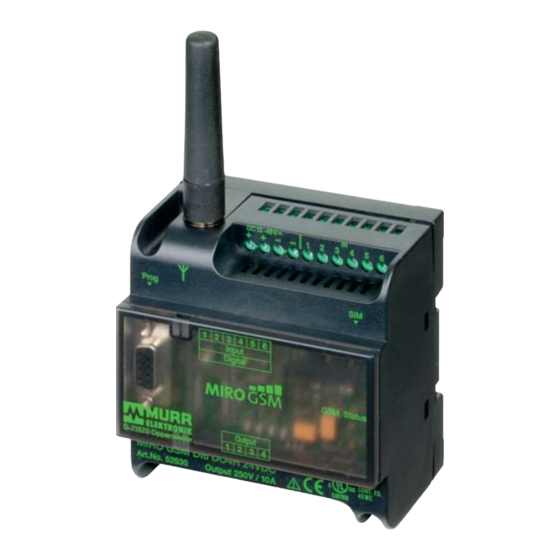
Manual MIRO GSM 8. Technical Data 8.1 Dimensional Layout 12 ... 48 VDC MIRO GSM D-71570 Oppenweiler MIRO GSM DI6 DO4R 24 VDC Art.No. 52530 Output 250V / 10A LISTED Fig. 40: MIRO GSM - dimensional layout www.comoso.com... -
Page 51: Technical Data
Manual MIRO GSM 8.2 Technical Data Art. No. 52530 MIRO GSM DI6 DO4R 24 V DC Art. No. 52531 MIRO GSM ADI6 DO4R 24 V DC Art. No. 52532 MIRO GSM DI6 DO4R 230 V AC Gerätebeschreibung / Device Description ... - Page 52 MIRO GSM Technische Daten / Technical data 52530 52531 52532 MIRO GSM DI6 MIRO GSM ADI6 MIRO GSM DI6 DO4R DO4R DO4R 24 V DC 230 V AC 24 V DC Speisung / Power Supply Nennbetriebsspannung / 12 … 24 V DC 110 …...
- Page 53 Manual MIRO GSM 52530 52531 52532 MIRO GSM DI6 DO4R MIRO GSM ADI6 DO4R MIRO GSM DI6 DO4R 24 V DC 24 V DC 230 V AC Analoge Eingänge I1 … I6 / Analog inputs I1 … I6 Eingangsbereich nominal / 0 …...
- Page 54 Manual MIRO GSM Sonstiges / Other: 52530 52531 52532 MIRO GSM DI6 DO4R MIRO GSM ADI6 MIRO GSM DI6 DO4R DO4R 24 V DC 230 V AC 24 V DC Allgemeine Daten / General data Abmessungen (H x B x T) / 80 x 90 x 59.5 mm...
-
Page 55: Accessories
9. Accessories Art. No. 52533 MIRO GSM Stummelantenne / Stub antenna Art. No. 52534 MIRO GSM Außenantenne mit 5 m Kabel / Antenna with 5 m cable Art. No. 52535 MIRO GSM Service- und Inbetriebnahme-Kit / Service and Start-up Kit Art.-No. -
Page 56: Overview Of Devices And Phone Numbers
Manual MIRO GSM Overview of Devices and Phone Numbers Devices Device type N° MIRO GSM Device ID Password Phone Number Modem Device type N° MIRO GSM Device ID Password Phone Numbers www.comoso.com... -
Page 57: Legal Provisions
Manual MIRO GSM Legal Provisions Exclusion of Liability Murrelektronik GmbH has checked the contents of this technical documentation for conformity with the hardware and software described therein. Deviations can not be excluded in individual cases. For this reason, Murrelektronik excludes the warranty for the correctness of its contents and any liability for errors, in particular full conformity. - Page 58 Murrelektronik GmbH|Falkenstraße 3, D-71570 Oppenweiler|P.O. Box 1165, D-71567 Oppenweiler Phone +49 7191 47-0|Fax +49 7191 47-130|info@murrelektronik.com|www.murrelektronik.com The information in this manual has been compiled with the utmost care. Liability for the correctness, completeness and topicality of the information is restricted to gross negligence. www.comoso.com...
Need help?
Do you have a question about the MIRO GSM and is the answer not in the manual?
Questions and answers