
Related Manuals for BERNSTEIN G3005A


Summary of Contents for BERNSTEIN G3005A
- Page 1 WC-Vorwandelement G3005A Support frame G3005A Bâti-support G3005A Sistema di installazione a parete G3005A MONTAGE- BEDIENUNGSEANLEITUNG - IIII / 2021...
- Page 2 WC-VORWANDELEMENT G3005A LIEFERUMFANG Beschreibung Menge Funktion Befestigungsschrauben Befestigungsset des Rahmens Wandhalterung Befestigung des Rahmens an der Wand Eckventil Einlass und Absperrung des Füllventils Zylinderschrauben Befestigung des Rahmens und Arretierung in der Wandhalterung Montagewinkel Zur Ausrichtung des Abflusssiphons Halterung Zur Befestigung des Abflusssiphons Ablaufbogen Abfluss des Keramik-WC Baustopfen Schutz der Anschlüsse während des Einbaus Anschlussrohr Verbindung zum Keramik-WC, kürzbares Anschlussrohr, mit Dichtung...
- Page 3 WC-VORWANDELEMENT G3005A INSTALLATIONSVARIANTEN Variante 1 1. Bitte halten Sie sich an die folgenden Montagewand Installationsanweisungen. Wir übernehmen keine Vorwandinstallation Haftung für Ausfälle und Schäden, die auf eine unsachgemäße Installation zurückzuführen sind. 2. Zeichnen Sie bitte vor der Installation die Befestigungspunkte der Vorwandinstallation an und ermitteln Sie die fertige Bodenoberfläche. Zeichnen Sie die Oberkante des Fertig Fußbodens (OK FFB) auf die Installationswand und folgen Sie ihr als Grundlinie von der NULL (0) Ebene aus.
-
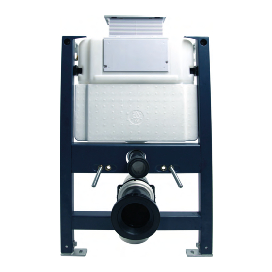
Page 4: Technische Zeichnung
WC-VORWANDELEMENT G3005A TECHNISCHE ZEICHNUNG Wasseranschluss mit seitlicher Anordnung Der Spülkasten wird über das Eckventil an die Wasserversorgung angeschlossen. 529 mm Montagewand 500 mm 165 ~ 200 mm 460 mm Gewinde des Eckventils: G ½“ Vorwandelement 230 mm 180 mm Ø110 mm Oberkante Fertig Fußboden OK FFB 375 mm Die Abmessungen von H1 und H2 sind variabel und abhängig vom WC. - Page 5 WC-VORWANDELEMENT G3005A Einbau des Ablaufsiphons Abwasserrohr Montagewinkel herausziehen Siphon montieren Halterung wieder verriegeln Metallrahmen in vertikaler und horizontaler Richtung ausrichten. Wandbefestigungen und Bodenbefestigungssets anbringen und die Wasserversorgungsleitung anschließen. Ziehen Sie die Verbindung zunächst Wandabstand und nur locker an und sichern Sie sie, Eckventil Höhe einrichten...
- Page 6 WC-VORWANDELEMENT G3005A Montage der Drückerplattenaufnahme am Spülkasten für die Frontbetätigung Spülkastenabdeckung hier Oben Montagezeichnung - Front Fixieren Sie die beiden Abdeckungen (Oben und Front) mit beigefügten Schrauben. Flexibler Bauschutz Bauschutzabdeckung mit Serviceöffnung hier Front Montage der Drückerplattenaufnahme am Spülkasten für die Betätigung von oben Flexibler Bauschutz mit Serviceöffnung...
- Page 7 WC-VORWANDELEMENT G3005A Verschalungsplatten verhindern, dass Schmutz in die Installation eindringen kann. (Nicht im Lieferumfang enthalten) Positionierung der Platten Abdeckung mit Abdeckung mit am Vorwandelement Drückerplatte von vorne Drückerplatte von oben Wandstärken variabel von 15 - 70 mm (von der jeweiligen Rahmenkante bis zur fertigen Oberfläche) ◄ Montage- Montage- rahmen rahmen Skizze für Einbau Skizze für Einbau mit Drückerplatte vorne...
- Page 8 WC-VORWANDELEMENT G3005A Montage des WC Tragen Sie Gleitmittel auf die Gummi- dichtungen der Verbindungsrohre auf und setzen Sie sie dann in die Keramik ein. Führen Sie das Zuflussrohr in den Spülkastenauslauf und das Verbindungsrohr in den Ablauf ein. Zeichnen Sie die Linien an, wie abgebildet. L1 + 5mm L2 + 3mm L1 ist der Abstand am Zuflussrohr + 5mm. L2 ist der Abstand am Ablaufrohr + 3mm. Zeichnen Sie die zweiten Kürzen Sie die Verbindungsrohre mit ent-...
- Page 9 WC-VORWANDELEMENT G3005A Montagezeichnung des internen Spülmechanismus. 4,5L - 6L Wasserlinie „CLICK“ Der interne Spülmechanismus ist bereits fertig montiert und das Bild dient nur als Referenz.
- Page 10 WC-Vorwandelement G3005A Support frame G3005A Bâti-support G3005A Sistema di installazione a parete G3005A MONTAGE- BEDIENUNGSEANLEITUNG - I / 2022 ASSEMBLY INSTRUCTIONS / NOTICE DE MONTAGE / ISTRUZIONI DI MONTAGGIO...
-
Page 11: Delivery Scope
WC-SUPPORT FRAME G3005A DELIVERY SCOPE Description Quantity Function Fixing screws Fixing set of the frame Wall bracket Fixing the frame to the wall Angle valve Inlet and shut-off of the filling valve Socket head cap screws 2 Fixing the frame and locking it in the wall bracket... -
Page 12: Installation Options
WC-SUPPORT FRAME G3005A INSTALLATION OPTIONS Option 1 1. Please adhere to the following installation instructions. Mounting wall We do not accept any liability for failures and damages Support Frame caused by improper installation. 2. Before installation, please draw the fixing points of the pre-wall installation and determine the finished floor surface. -
Page 13: Technical Drawing
WC-SUPPORT FRAME G3005A TECHNICAL DRAWING Water connection with lateral arrangement The cistern is connected to the water supply via the angle valve. 529 mm Mounting wall 500 mm 165 ~ 200 mm 460 mm Thread of the angle valve: G ½“... - Page 14 WC-SUPPORT FRAME G3005A Installing the drain siphon Wastewater pipe Pull out the mounting bracket Installing the siphon Lock the bracket back in place Align support frame in vertical and horizontal direction. Attach wall fixings and floor fixing sets and connect the water supply pipe.
- Page 15 WC-SUPPORT FRAME G3005A Mounting the handle plate holder on the cistern for front actuation Cistern cover Installation drawing - Front Fix the covers (Top and Front) with the enclosed screws. Flexible building protection Protection cover with service opening Front Mounting the lever handle plate holder on the cistern for actuation from above...
- Page 16 WC-SUPPORT FRAME G3005A Shuttering plates prevent dirt from entering the installation. (Not included in the scope of delivery) Positioning the panels Cover with pushplate on Front Cover with pushplate on Top on the support frame Wall thicknesses variable from 15 - 70 mm (from the respective frame edge to the finished surface) ◄...
- Page 17 WC-SUPPORT FRAME G3005A Assembly of the WC Apply glide agent to the rubber seals of the connecting tubes and then insert them into the ceramics. Insert the inlet pipe into the cistern outlet and the connecting pipe into the drain.
- Page 18 WC-SUPPORT FRAME G3005A Assembly drawing of the internal flushing mechanism. 4,5L - 6L Waterline „CLICK“ The internal flushing mechanism is already fully assembled and the picture is for reference only.
- Page 19 WC-Vorwandelement G3005A Support frame G3005A Bâti-support G3005A Sistema di installazione a parete G3005A MONTAGE- BEDIENUNGSEANLEITUNG - I / 2022 ASSEMBLY INSTRUCTIONS / NOTICE DE MONTAGE / ISTRUZIONI DI MONTAGGIO...
-
Page 20: Contenu De La Livraison
Bâti-support G3005A CONTENU DE LA LIVRAISON Description Quantité Fonction Vis de fixation Kit de fixation pour le cadre Support mural Fixation du cadre contre le mur Vanne équerre Entrée et obturation de la vanne de remplissage Vis à tête cylindrique Fixation du cadre et vérouillage dans le support mural... - Page 21 Bâti-support G3005A VARIANTES D‘INSTALLATION Variante 1 1. Veuillez suivre les instructions d’installations suivantes. Paroi de montage Nous déclinons toute responsabilité pour les Bâti-support dommages ou pannes résultant d’une installation non conforme, négligente ou incorrecte. 2. Avant l’installation, veuillez marquer les points de fixation de l’installation en applique et déterminer la...
- Page 22 Bâti-support G3005A DESSIN TECHNIQUE Le raccordement à l’eau avec disposition latérale La citerne est connectée à l‘alimentation en eau via la vanne d‘angle. 529 mm Paroi de montage 500 mm 165 ~ 200 mm 460 mm Filetage de la vanne équerre: G ½“...
- Page 23 Bâti-support G3005A Installation du siphon d‘écoulement Évacuation Retirer l’équerre de fixation Monter le siphon Verrouiller à nouveau le support Alignez le cadre métallique dans le sens vertical et horizontal. Installer les fixations murales les kits de fixation au sol et raccorder la conduite d’alimentation en eau.
- Page 24 Bâti-support G3005A Mise en place de la plaque de déclenchement au bâti-support pour actionnement vertical/en façade Couvercle de protection Vue d’en haut Plan de montage vertical, en façade Fixez les deux couvercles de protection (haut et façade) avec les vis fournies.
- Page 25 Bâti-support G3005A Panneaux de revêtement empêchent la saleté de pénétrer dans l’installation. (Non inclus dans la livraison) Positionnement des panneaux Protection avec plaque de Protection avec plaque de sur le bâti-support déclenchement en façade déclenchement en tablette Épaisseur de paroi variable de 15 - 70 mm (du bord du châssis respectif à...
- Page 26 Bâti-support G3005A Mise en place de la cuvette WC Appliquez du lubrifiant sur les joints en caoutchouc des tuyaux de raccordement, puis insérez-les dans la cuvette. Insérez le tuyau d’évacuation dans la sortie du réservoir de la chasse et le tube de raccordement dans l‘écoulement...
- Page 27 Bâti-support G3005A Schéma de montage du mécanisme de rinçage interne. 4,5L - 6L Ligne d‘eau „CLICK“ Le mécanisme de rinçage interne est déjà assemblé et l’image sert uniquement de référence.
Need help?
Do you have a question about the G3005A and is the answer not in the manual?
Questions and answers