Advertisement
®
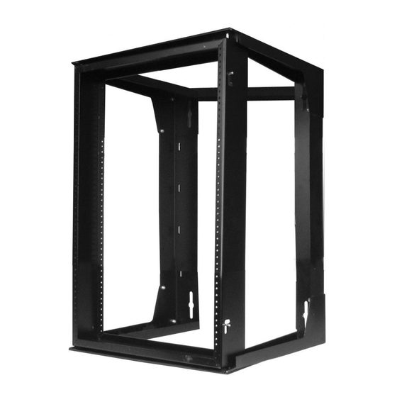
Hubbell Premise Wiring Instruction Sheet
This instruction sheet applies to the following Hubbell Premise Wiring Part Numbers:
Required for Installation - 3/8" Nut Driver & Phillips Screwdriver
Consists Of The Following Parts:
T I
E
M
Q
T
Y
D
E
S
C
R
P I
T
1
2
o T
p
&
B
t o
o t
2
1
S
w
n i
g
F
a r
m
3
2
S
d i
e
B
a r
e c
4
1
R
e
r a
B
a r
e c
5
4
#
1
0
-
3
2
A
c
6
8
#
1
0
-
3
2
x
1
7
5
0
#
1
2
-
2
4
x
1
8
2
1
4 /
-
2
0
3 x
4 /
9
2
B
a l
k c
N
y
o l
n
Special Notes:
Item #7 used to mount equipment to swing racks
S
w
n i
g
V
e
t r
c i
l a
R
a
c
k
G
a
u
R
a
c
k
M
o
u
t n
n i
g
U
i n
s t
S
e t
S
z i
e
S
p
a
c
e
2
" 4
1
2
2
1
0 .
" 0
1
3
" 6
1
9
3
3
2 .
" 5
1
4
" 8
2
6
4
5
5 .
" 0
1
Place the Back Brace onto the four threaded studs on the two
Side Brace Assemblies. Secure with four #10 -32 Nylon Acorn
Nuts. Tighten with 3/8" nut driver.
Install the Top / Bottom Braces to the outside of the two Side
Brace Assemblies with eight #10 - 32 x 1/4" Phillips Pan Hd.
Screws. The large formed edge of the Top Bottom Braces
mount towards the rear and the inside of the swing rack.
The 19" EIA Swing Frame Rack can be hinged (retractable
pin) on either side. Customer needs to determine which side
is to open. To open, simply retract both pins (top and bottom)
and then open the Swing Frame Rack similar to that of a door.
WALL MOUNT RACK
HPWWMR24
HPWWMR36
HPWWMR48
O I
N
m
B
a r
e c
e
A
s
y s
A
s
y s
P
a
n
l e
o
n r
N
, t u
B
a l
c
, k
S
f l e
L -
o
k c
n i
g
4 /
L "
P
l i h
P
a
n
H
D
S
c
e r
, w
T
p y
e
2
, 3
B
a l
2 /
L "
P
p
l i h
P
a
n
H
D
S
c
e r
, w
T
p y
e
2
, 3
B
L "
P
i h
8 l
2
F
t a l
H
e
a
d
S
c
e r
w
W
/
N
y
o l
n
S
p
a
c
r e
0 (
5 .
0
O
, D
0
2 .
6
I
, D
0
1 .
8
7
T
) H
g
e
M
o
u
t n
n i
g
F
a r
m
e
O
v
e
a r
l l
l e
H
o
e l
s
D
e
p
h t
H
e
g i
t h
4
#
1
2
2 -
4
" 4
2
4
7 .
" 6
4
#
1
2
2 -
4
" 4
3
6
0 .
" 1
2
#
1
2
2 -
4
" 4
4
8
0 .
" 1
HPWWMR24D
HPWWMR36D
HPWWMR48D
k c
a l
k c
L
o
k c
n i
g
P
l e
t e l
O
v
e
a r
l l
O
v
e
a r
l l
W
e
g i
t h
W
d i
h t
D
e
p
h t
C
a
p
a
i c
y t
2
0
5 .
6
" 2
1
" 8
1
0
0
2
0
5 .
6
" 2
1
" 8
1
0
0
2
0
5 .
6
" 2
1
" 8
1
0
0
Control No.
77864001
Rev.
D
Date:
1
5
1
Page
1
of
2
07MAY02
3
Advertisement
Table of Contents

Subscribe to Our Youtube Channel
Related Manuals for Hubbell HPWWMR24

Summary of Contents for Hubbell HPWWMR24
- Page 1 Page Hubbell Premise Wiring Instruction Sheet 77864001 WALL MOUNT RACK Rev. Date: 07MAY02 This instruction sheet applies to the following Hubbell Premise Wiring Part Numbers: HPWWMR24 HPWWMR24D HPWWMR36 HPWWMR36D HPWWMR48 HPWWMR48D Required for Installation - 3/8" Nut Driver & Phillips Screwdriver Consists Of The Following Parts: &...
- Page 2 (2) are secured into the rear section that has been mounted to the wall. Be sure all screws, nuts and mounting hardware are tightened befor loading with equipment Hubbell Premise Wiring, HUBBELL INCORPORATED (Delaware) 14 Lord's Hill Rd, Stonington CT 06378 (800) 626-0005, Fax (860) 535-8328 www.hubbell-premise.com...
Need help?
Do you have a question about the HPWWMR24 and is the answer not in the manual?
Questions and answers