Table of Contents
Advertisement
Quick Links
PZ115E User Manual
E-621.SR
LVPZT Controller/Amplifier Module
Release: 2.3.0
Date: 2021-09-21
Physik Instrumente (PI) GmbH & Co. KG, Auf der Roemerstrasse 1, 76228 Karlsruhe, Germany
Phone +49 721 4846-0, Fax +49 721 4846-1019, Email info@pi.ws,
This document describes the
following product:
E-621.SR
LVPZT Controller/Amplifier, Single Channel, for
Strain Gauge Sensors
With servo controller submodule and computer
interface and command interpreter submodule.
Capacitive sensor E-621 versions are described in a
separate manual, PZ160E.
www.pi.ws
Advertisement
Table of Contents

Related Manuals for PI E-621.SR


Summary of Contents for PI E-621.SR
- Page 1 Capacitive sensor E-621 versions are described in a separate manual, PZ160E. Physik Instrumente (PI) GmbH & Co. KG, Auf der Roemerstrasse 1, 76228 Karlsruhe, Germany Phone +49 721 4846-0, Fax +49 721 4846-1019, Email info@pi.ws, www.pi.ws...
- Page 2 Physik Instrumente (PI) GmbH & Co. KG is the owner of the following company names and trademarks: PI®, NanoCube®, PICMA®, PILine®, NEXLINE®, PiezoWalk®, NEXACT®, Picoactuator®, PInano®, PIMag®, Q-Motion® Notes on brand names and third-party trademarks: Microsoft® and Windows® are registered trademarks or trademarks of Microsoft Corporation in the USA and/or other countries.
- Page 3 About This Document Users of This Manual This manual is designed to help the reader to install and operate the E-621.SR LVPZT Controller/Amplifier Module. It assumes that the reader has a fundamental understanding of basic servo systems, as well as motion control concepts and applicable safety procedures.
-
Page 4: Table Of Contents
4.1.2 Open-Loop Sensor Range Adjustment ........28 4.1.3 Servo-Control Static Gain Calibration ........30 Servo-Control Dynamic Characteristics ........32 Electronics Details E-621.SR Block Diagram ............33 Components and Adjustment Elements ........34 5.2.1 Jumpers ..................35 5.2.2 Switches ................... 36 5.2.3 Potentiometers ................. - Page 5 Contents Customer Service Old Equipment Disposal Technical Data Specifications ................44 Frequency Response Diagram ..........46 Pin Assignments ..............47 9.3.1 32-Pin Main Connector ............47 9.3.2 Strain Gauge Sensor Wiring ............ 48 10. Appendix 10.1 Lifetime of PICMA® Actuators ..........49 10.2 European Declarations of Conformity ........
-
Page 6: Introduction
(LVPZT). The E-621.SR provides DC sensor processing for usage with strain gauge sensors (SGS; via E801B1008 sensor submodule). The E-621.SR comes with an E-802 Servo Controller and an E- 816 Computer Interface and Command Interpreter installed as standard. - Page 7 E-816 User Manual. E-802 User Manual (PZ150E) and E801B1008 User Manual (PZ117E) In addition to the E-816 computer interface module, the following submodules are integrated in the E-621.SR: E-802.55 servo controller submodule E801B1008 sensor processing submodule...
-
Page 8: Intended Use
E-500.621 or E- 501.621 provided by PI. Based on its design and realization, the E-621.SR LVPZT Controller/Amplifier Module is intended to drive capacitive loads, in the present case, piezoceramic actuators. The E- 621.SR must not be used for applications other than stated in... -
Page 9: Safety Precautions
Introduction Safety Precautions DANGER High Voltage: Read This Before Operation: E-621.SR LVPZT Controller/Amplifier Modules generate voltages up to 130 V for driving LVPZTs. The output power may cause serious injury. When working with these devices or using PZT products from other manufacturers we strongly advise you to follow general accident prevention regulations. - Page 10 CAUTION The E-621 main connector pinout is not compatible with the PI EURO board modules of the E-500 series (e.g. E- 509 servo controller or E-50x amplifier). CAUTION For successful operation of two or more E-621.CRs—...
- Page 11 Introduction CAUTION Calibration should only be done after consultation with PI, otherwise the internal configuration data may be destroyed by erroneous operation. CAUTION Thermally stable systems have the best performance. For a thermally stable system, switch on the E-621 at least one hour before you start working with it.
-
Page 12: Unpacking
Introduction Unpacking According to your order, the E-621.SR LVPZT Controller/Amplifier Module comes separately or installed in an E-500.621 or E-501.621 chassis. Unpack the system with care. Compare the contents against the items covered by the contract and against the packing list. The following items should be included with an E-621 unit: ... -
Page 13: Quick Start
Line Power and Fuses This section is only relevant if the E-621 comes installed in an E-500.621 or E-501.621 chassis provided by PI. The power connection and the line fuses are located on the rear panel of the E-500.621 or E-501.621 chassis. The chassis is equipped with a wide-range power supply and with fuses that are admissible for both 115 V and 230 V operation. -
Page 14: Installation
(envelopes, foam). Electronic subassemblies must always be kept and transported/shipped in conductive packaging. Make sure that no conductive particles of any kind (metallic dust or shavings, broken pencil leads, loose screws) contact the device circuitry. www.pi.ws E-621.SR PZ115E Release 2.3.0 Page 11... - Page 15 (588). For pinout see “32-Pin Main Connector” on p. 47. CAUTION E-621 is only compatible with E-50x.621 chassis but incompatible with other chassis of PI’s E-500-series. NOTE All front-panel connections except of the USB lines are duplicated on the 32-pin main connector.
-
Page 16: First Steps
Notes: The servo must be ON in analog mode, when you want to work with a computer-generated signal (e.g. from a DAQ board) and PI’s drivers for NI LabVIEW (see step 5 below). www.pi.ws E-621.SR PZ115E Release 2.3.0... - Page 17 (i.e. not connected to pin 14a or 14c) Connect the piezo positioners/actuators to the proper E-621.SR units. If your system was calibrated by PI, the controllers and positioners are not interchangeable. Respect the assignment given by the serial numbers marked on the calibration label of the controller Connect a suitable signal source to the “ANALOG...
- Page 18 (servo ON), then a zero-point adjustment is necessary. Follow the instructions for zero-point adjustment given in Section 4.1.1 on p. 26. To avoid an overflow of the amplifier in open-loop operation, do not exceed the allowable control input range. www.pi.ws E-621.SR PZ115E Release 2.3.0 Page 15...
-
Page 19: Operation
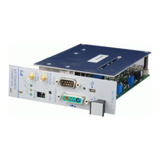
Operation Operation Front Panel Elements NOTE All front-panel connections except of the USB lines are duplicated on the 32-pin main connector. Fig. 3: E-621.SR Front Panel www.pi.ws E-621.SR PZ115E Release 2.3.0 Page 16... - Page 20 The control input voltage can also be a computer- generated analog signal (e.g. from a DAQ board). You can use PI’s drivers for NI LabVIEW from the PI software CD to generate that analog signal. See “Control Modes” on p. 19 for details ...
- Page 21 2-conductor coaxial LEMO ERA.00.250 for piezo actuator drive voltage output. PZT ground is on the outer conductor (tied to case), PZT+ on the inner conductor. The drive voltage output is in the range of -30 to 130 V. www.pi.ws E-621.SR PZ115E Release 2.3.0 Page 18...
-
Page 22: Modes Of Operation
The current control mode of the E-621 determines the applicable control sources for the output voltage and hence for the axis motion. It is selected with the “Settings” DIP switches on the E-621 front panel. www.pi.ws E-621.SR PZ115E Release 2.3.0 Page 19... - Page 23 “Lifetime of PICMA® Actuators” on p. 49 for details. The analog control input can be a computer-generated analog signal (e.g. from a DAQ board). You can use PI’s drivers for NI LabVIEW from the PI software CD to generate that analog signal.
-
Page 24: Servo Modes (On / Off)
SVO command via the E-816 computer interface submodule. By default and when installed in an E-50x.621 chassis from PI, pin 28a is not connected to pin 14a or 14c and hence set to servo off (open-loop operation) ... - Page 25 Closed-loop operation offers both drift-free and hysteresis- free positioning as well as immunity to load variations. PI’s standard calibration procedure assures that the piezo actuator reaches its nominal expansion when that position is commanded.
-
Page 26: Networking On I C Bus
C Bus It is possible to command up to twelve E-621.SRs over a single RS-232 or USB interface from a single host PC. The E-621.SR connected to the RS-232 or USB link (the master) relays commands to the other units (slaves) on the network. -
Page 27: User Electronics And Sensor Monitor Signal
It may be necessary to add a 4.7 nF (ceramic NP0 or COC type) to the input connector. Use shielded cable if possible, otherwise make sure the lead pair is tightly twisted. Fig. 4: Electronics on Sensor Monitor line with required input capacitance www.pi.ws E-621.SR PZ115E Release 2.3.0 Page 24... -
Page 28: Calibration
47 for details. Sensor Connection and Adjustment If you inform PI about your application, your E-621.SRs will be fully calibrated before being shipped. It is usually not necessary for you to do anything more than adjust the zero point before operating the system. -
Page 29: Open-Loop Zero-Point Adjustment
Calibration CAUTION Calibration should only be done after consultation with PI, otherwise the internal configuration data may be destroyed by erroneous operation. Position sensors are connected to the “SENSOR” socket on the E-621 front panel, see the wiring diagram on p. 48. The E- 621.SR provides DC sensor processing (it is equipped with the... - Page 30 “SENSOR MONITOR” SMB socket on the front panel with a voltmeter 7. Correct zero Adjust the Zero potentiometer on the front panel so that the sensor- monitor signal is +1 V www.pi.ws E-621.SR PZ115E Release 2.3.0 Page 27...
-
Page 31: Open-Loop Sensor Range Adjustment
When a module removed from the chassis must be operated, use a 32-pin extension connector (P-895.00, not included). Voltages of up to 130 V can be exposed. Do not touch internal conductors. www.pi.ws E-621.SR PZ115E Release 2.3.0 Page 28... - Page 32 10 V. See the User Manual of the E801B1008 Sensor Processing Submodule for component designation and location. 10. Recheck It may be necessary to repeat the last steps until stable readings are obtained. www.pi.ws E-621.SR PZ115E Release 2.3.0 Page 29...
-
Page 33: Servo-Control Static Gain Calibration
When a module removed from the chassis must be operated, use a 32-pin extension connector (P-895.00, not included). Voltages of up to 130 V can be exposed. Do not touch internal conductors. www.pi.ws E-621.SR PZ115E Release 2.3.0 Page 30... - Page 34 This adjustment can only be done accurately for one control mode (analog mode or computer-controlled mode). If you use the unadjusted mode, 1% error in the sensor monitor output voltage can be expected. www.pi.ws E-621.SR PZ115E Release 2.3.0 Page 31...
-
Page 35: Servo-Control Dynamic Characteristics
5%. To deactivate the notch filter and slew rate limiter, use jumper J1 in position 2-3 to remove the E-802 from the circuit entirely (see block diagram below). www.pi.ws E-621.SR PZ115E Release 2.3.0 Page 32... -
Page 36: Electronics Details
Depending on the DIP switch settings, the resultant signal will be used either as control input, or as digital input for triggering. If the signal on the SMB socket is to be used as trigger, DC offset must be deactivated or set to 0. www.pi.ws E-621.SR PZ115E Release 2.3.0 Page 33... -
Page 37: Components And Adjustment Elements
Components and Adjustment Elements See also the E801B1008 and E-802 User Manuals for adjustment elements on those submodules which are not described here. Fig. 6: E-621.SR (viewed from component side, with bottom edge on top) component locations; adjustment elements shown in default settings www.pi.ws... -
Page 38: Jumpers
JP107 - JP109 shift the voltage range of the sensor processing circuitry. They must remain as set at the factory, i.e. for use with an E-802 servo controller submodule (positive polarity, 0-10 V) Fig. 7: E-621.SR sensor processing output settings www.pi.ws E-621.SR PZ115E Release 2.3.0... -
Page 39: Switches
See also the User Manual of the respective submodule for more details. E801B1008 Sensor Processing Submodule Sensor excitation and processing is implemented on a small, replaceable submodule. SGS versions have an E801B1008 submodule which provides DC sensor excitation and readout. www.pi.ws E-621.SR PZ115E Release 2.3.0 Page 36... -
Page 40: E-802 Servo Controller Submodule
Note and respect component-side orientation. For calibration procedures, see "Servo-Control Static Gain Calibration", p. 30 and "Servo-Control Dynamic Characteristics", p. 32. The E-802 submodule is described in detail in a separate user manual. www.pi.ws E-621.SR PZ115E Release 2.3.0 Page 37... -
Page 41: Troubleshooting
(excursions to -3 or +13 V may cause overflow, especially with servo on, and reduce actuator lifetime). If you generate the analog signal with a DAQ board in a PC running LabVIEW and using PI’s drivers for NI LabVIEW, check the driver and the DAQ board for proper operation. www.pi.ws E-621.SR PZ115E Release 2.3.0... - Page 42 The high voltage output of the E-621.SR is deactivated If the internal temperature goes out of range (75 °C or higher), the high voltage output of the E-621.SR will be deactivated. In that case the mechanics will no longer move.
- Page 43 If you use the USB interface and after switching on the E- 621.SR a dialog appears with the message that the driver for the hardware is missing: Install the USB driver from the PI software CD. The installation files for the USB drivers are located on the CD in the directory \SingleSetups.
- Page 44 Wrong combination of driver routines/Vis Check if system runs with Terminal program. If so, read the information in the corresponding manual for the PC software and compare the sample code on the PI software CD with your program code. www.pi.ws E-621.SR PZ115E Release 2.3.0...
-
Page 45: Customer Service
Customer Service Customer Service For inquiries and orders, contact your PI sales engineer or send us an email (mailto:service@pi.de). If you have any questions concerning your system, provide the following information: Product codes and serial numbers of all products in the system ... -
Page 46: Old Equipment Disposal
PI equipment that was first put into circulation after 13 August 2005, free of charge. If you have such old equipment from PI, you can send it to the following address postage-free: Physik Instrumente (PI) GmbH & Co. KG Auf der Römerstr. -
Page 47: Technical Data
Interface / communication USB, RS-232 (9-pin Sub-D connector, 9.6 - 115.2 kBaud), 24-bit A/D and 20-bit D/A resolution Piezo connector LEMO ERA.00.250.CTL Sensor connection LEMO EPL.0S.304.HLN Control input / trigger input socket Sensor monitor socket www.pi.ws E-621.SR PZ115E Release 2.3.0 Page 44... - Page 48 Technical Data E-621.SR Controller network up to 12 channels Command set PI General Command Set (GCS) User software PIMikroMove Software drivers NI LabVIEW drivers, DLLs Supported functionality Wave table with 256 data points, external trigger, 16 macros DC Offset External potentiometer (not included), adds 0...
-
Page 49: Frequency Response Diagram
Technical Data Frequency Response Diagram Fig. 10: E-621 open-loop frequency response with various piezo loads. Values shown are capacitance in μF www.pi.ws E-621.SR PZ115E Release 2.3.0 Page 46... -
Page 50: Pin Assignments
**If E-621s are networked outside a single E-50x.621 chassis, the SCL and SDA bus lines are limited to a maximum length of 1 m and a maximum capacitance of 400 pF. ***Pins 14a and 14c should be connected to a protective ground www.pi.ws E-621.SR PZ115E Release 2.3.0 Page 47... -
Page 51: Strain Gauge Sensor Wiring
Technical Data 9.3.2 Strain Gauge Sensor Wiring Fig. 11: Pin configurations and wiring for various different positioners www.pi.ws E-621.SR PZ115E Release 2.3.0 Page 48... -
Page 52: Appendix
-3 to 13 V is possible (results in -30 to 130 V piezo voltage in open-loop operation), but will reduce the actuator lifetime accordingly. Fig. 12: Interdependency between the mean MTTF of a PICMA® actuator and the value of the voltage applied www.pi.ws E-621.SR PZ115E Release 2.3.0 Page 49... - Page 53 =100) result in an approximate MTTF of 105,000 h, i.e. more than 11 years (see markings on the diagrams). Read “Piezo Technology - Piezoceramic Components & Actuators” on our website for detailed information. www.pi.ws E-621.SR PZ115E Release 2.3.0 Page 50...
-
Page 54: European Declarations Of Conformity
Appendix 10.2 European Declarations of Conformity For the E-621.SR, Declarations of Conformity have been issued in accordance with the following European regulations: Low Voltage Directive (LVD) EMC Directive RoHS Directive The applied standards certifying the conformity are listed below. ...
Need help?
Do you have a question about the E-621.SR and is the answer not in the manual?
Questions and answers