Table of Contents
Advertisement
Quick Links
PZ235E User Manual
E-831.05 Piezo Amplifier Module
Release: 1.0.0
Date: 2012-03-06
This document describes the
following product:
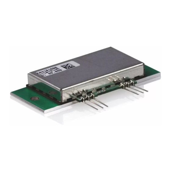
E-831.05
Piezo Amplifier, Miniature OEM Module,
1 Channel, -30 to 130 V
© Physik Instrumente (PI) GmbH & Co. KG
Auf der Römerstr. 1 ⋅ 76228 Karlsruhe, Germany
Tel. +49-721-4846-0 ⋅ Fax: +49-721-4846-1019
info@pi.ws ⋅ www.pi.ws
Advertisement
Table of Contents

Related Manuals for PI E-831.05


Summary of Contents for PI E-831.05
- Page 1 This document describes the following product: E-831.05 Piezo Amplifier, Miniature OEM Module, 1 Channel, -30 to 130 V © Physik Instrumente (PI) GmbH & Co. KG Auf der Römerstr. 1 ⋅ 76228 Karlsruhe, Germany Tel. +49-721-4846-0 ⋅ Fax: +49-721-4846-1019 info@pi.ws ⋅ www.pi.ws...
- Page 2 E-831.05 Single-Channel LVPZT Amplifier User Manual PZ235E Release 1.0.0 info@pi.ws Page 2...
-
Page 3: Table Of Contents
Block Diagram ................8 3.1. Power Supplies ................8 3.2. Technical Data ............9 Pin Assignment ............10 Dimensions ............... 10 © Copyright 2012 by Physik Instrumente (PI) GmbH & Co. KG Release: 1.0.0 File:E-831_05_User_PZ235E100.doc, 182784 Bytes Release 1.0.0 info@pi.ws Page 3... -
Page 4: Introduction
1.1. Intended Use The E-831.05 is a laboratory device as defined by DIN EN 61010-1. It is intended to be used in interior spaces and in an environment which is free of dirt, oil and lubricants. The E-831.05 must be installed in a suitable case before start-up. -
Page 5: General Safety Instructions
Improper use can result in personal injury and/or damage to the E-831.05. Only use the E-831.05 for its intended purpose, and only use it if it is in a good working order. Read the user manual. - Page 6 Install the E-831.05 in a metal case that is connected to a protective earth conductor. Connect at least one of the GND pins of the E-831.05 to the case in which the E-831.05 is installed so that it is conductive.
-
Page 7: Measures During Start-Up And Operation
Supply voltages that are too high or incorrectly connected can cause damage to the module. No limiting components are included. Do not exceed the supply voltage range (see p. 9) for which the E-831.05 is specified. Only operate the E-831.05 when the supply voltages are properly connected (for pin assignment, see p. -
Page 8: Amplifier Description
3.2. Power Supplies The E-831.05 requires voltages in the range of -28 to -38 V and 127 to 137 V. To prevent the customer from having to generate such untypical voltages PI offers suitable power supply modules. -
Page 9: Technical Data
E-831.05 Single-Channel LVPZT Amplifier User Manual PZ235E The solution PI provides is to make possible synchronization of the power supply with an external clock. In complex systems, or when the master clock is much higher and the various frequencies are made by dividers, more sophisticated synchronization circuits are sometimes necessary. -
Page 10: Pin Assignment
*Connect at least one of the GND pins of the E- 831.05 to as protective earth conductor: 1. Install the E-831.05 in a metal case that is connected to a protective earth conductor. 2. Connect at least one of the GND pins of the E- 831.05 to the case in which the E-831.05 is...
Need help?
Do you have a question about the E-831.05 and is the answer not in the manual?
Questions and answers