Table of Contents
Advertisement
Quick Links
WARNINGS AND CAUTIONS
• TO AVOID FIRE, SHOCK, OR DEATH; TURN OFF POWER at circuit breaker or fuse and test that power is off before wiring!
• To be installed and/or used in accordance with appropriate electrical codes and regulations.
• If you are unsure about any part of these instructions, consult an electrician.
• SAVE THESE INSTRUCTIONS.
For the following Models:
35A00-1 Leviton 600W Dimmer Switch, 35A00-1CFL 600W CFL/LED Dimmer, 35A00-3 Leviton 600W Non-Dimming
Switch (collectively referred to as Leviton UPB™ Wall Switch, in this document), and 37A00-1 Leviton Auxiliary Switch
NOTE: All Leviton UPB™ Wall Switches require a neutral (white) connection wire.
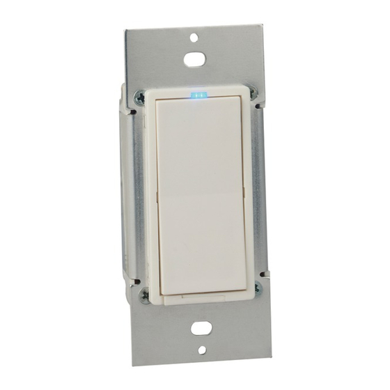
Leviton UPB™ Wall Switch Overview
The Leviton UPB™ Wall Switch (Figure 1) allows for local control of lighting by using the rocker switch. It also
incorporates the UPB™ two-way powerline communication technology that gives it the ability to be remotely controlled by
UPB™ compatible controllers. The Leviton UPB™ Wall Switch is also capable of transmitting UPB™ messages (including
current light level) when the rocker switch is turned on, turned off, brightened, or dimmed.
Each switch can be configured to custom fit an individual's lifestyle and desires. The Leviton Dimmer Switch is capable of
storing up to 16 preset light levels and fade rates to create powerful lighting scenes. The Leviton Non-Dimming Switch is
used to control such loads as fluorescent lights and ceiling fans.
Figure 1 - Leviton UPB™ Wall Switch
LED
INDICATOR
BLACK
TOP
(ON/BRIGHT)
WHITE
RED
YELLOW
BOTTOM
(OFF/DIM)
AIR-GAP SWITCH
LEVER GROOVE
GREEN
GROUND
Leviton Auxiliary Switch Overview
The 37A00-1 Leviton Auxiliary Switch (Figure 2) is an optional companion device used with the Leviton UPB™ Wall
Switch for multi-way circuits. The Leviton Auxiliary Switch has a rocker switch that controls the lighting load in the exact
same manner as the rocker switch on the Leviton UPB™ Wall Switch.
Figure 2 – Leviton Auxiliary Switch
LED
INDICATOR
BLACK
TOP
(ON/BRIGHT)
GRAY
BLUE
YELLOW
BOTTOM
(OFF/DIM)
LEVITON UPB™ WALL SWITCH AND AUXILIARY SWITCH
Installation Instructions and User's Guide
Changing Switch Color
The color of the Leviton UPB™ Wall Switch and Auxiliary Switch may be changed to complement the interior décor. The
Leviton UPB™ Wall Switch and Auxiliary Switch is supplied with a white switch plate. Additional colors are available;
contact your Leviton distributor for more information. When changing the switch plate, make sure that the switch is
disconnected from all power, and proceed as follows:
LINE
NEUTRAL
LOAD
The switch plate attaches to the Leviton UPB™ Wall Switch and Auxiliary Switch with two latches on the right and two on
the left. Using a small-bladed screwdriver, gently depress the upper and lower latch on one side while lifting up on the
CONTROL
plate. Once the latches are released on one side, remove the switch plate from the other side.
1. Align the latches of the new switch plate to the openings on the mounting plate and gently snap into place.
INSTALLATION INSTRUCTIONS
The Leviton UPB™ Wall Switch is wired directly to the lighting circuit and can be controlled by adding one or more optional
Leviton Auxiliary Switches producing multi-way circuits. Multi-way circuits make it possible for a group of switches to
control the same light or set of lights. This section will illustrate how to make the connections.
NOTES:
1. Refer to Figures 1 and 2 to determine the wire colors for each connection.
2. All Leviton UPB™ Wall Switches require a neutral (white) connection.
3. The Line (black) wire must be accessible for the installation of all Leviton Auxiliary Switches. This wire may be
connected to either phase of the 120/240V supply. The blue and/or gray wire on the Leviton Auxiliary Switch can be
connected to either earth ground or neutral. The blue and/or gray wire is only used to light the LED on the switch. This
LED only indicates that power is applied and serves as a night-light. Connect the blue wire only to light the LED blue.
Connect the gray wire only to light the LED red. Connect both the blue wire and the gray wire to light the LED magenta.
Air-Gap Switch Lever
The Leviton UPB™ Wall Switch has an air-gap switch lever that will remove all power from the load for safe switch
installation and light bulb replacement. To activate the air-gap switch, using your fingernail, pry open the lever at the
groove
(Figure 1). Swing the lever fully open so that it is perpendicular to the bottom rim (Figure 4). After servicing, push the
lever fully closed so that it is parallel to the bottom rim. The lever must be pushed fully closed for normal operation.
LINE
*NEUTRAL
(FOR RED INDICATOR)
*NEUTRAL
(FOR BLUE INDICATOR)
CONTROL
Cat. No. 35A00-1
INSTALLATION AND OPERATING INSTRUCTIONS
WARNINGS AND CAUTIONS
• To reduce the risk of overheating and possible damage to other equipment, when configured as dimming-capable, DO NOT
install to control a receptacle, a motor-operated appliance, or a transformer-supplied appliance.
• Use this device with copper or copper-clad wire only.
• For indoor use only.
Figure 3 – Changing Switch Color
Figure 4 – Air-Gap Switch Lever
Installation Procedure
1. Be sure that all power to the load has been disconnected by turning off the circuit breaker.
2. If applicable, remove the faceplate from the existing wall switch, remove the existing wall switch from the wall box, and
disconnect the wires from the existing wall switch. Identify the "Line", "Neutral", "Load" and "Traveler" (if applicable) wires.
3. Be sure that the air-gap switch lever on the Leviton UPB™ Wall Switch is fully open.
4. Remove 3/4" of insulation from each of the wires on the Leviton UPB™ Wall Switch. Install the Leviton UPB™ Wall
Switch by connecting wires per wiring configuration shown in Figure 5.
5. Install any optional Leviton Auxiliary Switch per wiring configuration shown in Figure 5.
6. After all connections have been made, be certain that all wire connectors are firmly attached and there is no exposed
copper.
7. Gently place the wires and Leviton UPB™ Wall Switch into the wall box with the LED at the top of device. Using the
supplied screws, attach the Leviton UPB™ Wall Switch to the wall box.
8. Before installing the faceplate, restore power to the circuit, and then fully close the air-gap switch lever.
9. After testing the Leviton UPB™ Wall Switch and Auxiliary Switch for proper local operation (see Table 2 and Table 3),
install a Decora
®
faceplate over each switch.
Leviton UPB™ Wall Switch De-Rating
In two-gang installations, there is no need to de-rate the 35A00-1, 35A00-1CFL, or 35A00-3. In three-gang installations,
each switch must be de-rated from 600W to 500W.
Table 1 – Leviton Wall Switch De-Rating
Model
Device Maximum Load
Next to One Dimmer
35A00-1
600W
600W
35A00-1CFL
600W
600W
35A00-3
600W
600W
Leviton DIMMER SWITCH OPERATION
The Leviton Dimmer Switch has many configurable items that can be set using the UPB™ UPStart configuration software.
The following describes the operation of the Leviton Dimmer Switch in its factory default configuration.
Local Rocker Switch Operation
The Leviton Dimmer Switch has a rocker switch that can be used to control the lighting load as follows.
Table 2 - Leviton UPB™ Dimmer Switch Local Operation
Rocker Event
Top Rocker
Single-Tap
Brightens the light to 100% (on) at
default fade rate and restarts auto
shut-off timer (if applicable).
Double-Tap
Snaps the light to 100% (on) and
overrides auto shut-off.
Hold
Starts fading (brightening) the light
towards 100% at default fade rate
and restarts auto shut-off timer (if
applicable).
Release
Stops brightening the light and
restarts auto shut-off timer (if
applicable).
Leviton NON-DIMMING SWITCH OPERATION
The Leviton Non-Dimming Switch has many configurable items that can be set using the UPB™ UPStart configuration
software. The following describes the operation of the Leviton Non-Dimming Switch in its factory default configuration.
Local Rocker Switch Operation
The Leviton Non-Dimming Switch has a rocker switch that can be used to control the load as follows.
Table 3 – Leviton Non-Dimming Switch Local Operation
Rocker Event
Top Rocker
Single-Tap
Turns the load on and starts auto
shut-off timer (if applicable).
PK-93406-10-00-5A
AR2243
(35I00-1)
ENGLISH
Next to Two Dimmers
500W
500W
500W
Bottom Rocker
Fade the light to 0% (off) at default
fade rate.
Snaps the light to 0% (off).
Starts fading (dimming) the light
towards 0% at default fade rate.
Stops dimming the light.
Bottom Rocker
Turns the load off.
Advertisement
Table of Contents

Related Manuals for Leviton 35A00-1


Summary of Contents for Leviton 35A00-1
- Page 1 Each switch can be configured to custom fit an individual’s lifestyle and desires. The Leviton Dimmer Switch is capable of 7. Gently place the wires and Leviton UPB™ Wall Switch into the wall box with the LED at the top of device. Using the storing up to 16 preset light levels and fade rates to create powerful lighting scenes.
- Page 2 Leviton’s control.Leviton is not responsible for issues related to improper installation, including failure to follow written Installation and operation instructions, normal wear and tear, catastrophe, fault or negligence of the user or other problems external to the Product.Toviewcompletewarrantyandinstructionsforreturningproduct,pleasevisitusatwww.leviton.com.
Need help?
Do you have a question about the 35A00-1 and is the answer not in the manual?
Questions and answers