Table of Contents
Advertisement
Quick Links
Advertisement
Table of Contents

Related Manuals for Dover HydroSystems Superdos 15 0.3


Summary of Contents for Dover HydroSystems Superdos 15 0.3
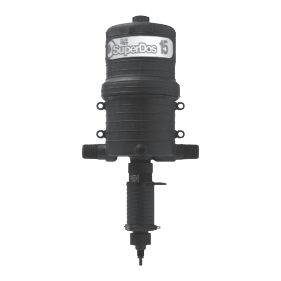
- Page 1 Operating Manual Model 0.3% Model 2.5% Model 2.5% WSP Model 5% Fluid Flow Range: 0.04 gpm to 15 gpm 10 lph to 3,400 lph Injection Range Dosage: 0.025% to 5% 1:4000 to 1:20 Operating Pressure: 3 to 60 psi* 0,21 to 4,1 bar* *Specifications vary by model.
- Page 3 Quick Start-up Part # 013824 Rev. J...
-
Page 4: Operating Principle
Operating Principle Accurate and Reliable Installed directly in the fluid supply line, the injector operates without electricity, using fluid (water) pressure as the power source. The fluid drives the injector, which pulls the required percentage of concentrate directly from the chemical solution container. Inside the Hydro patented mixing chamber, the concentrate is mixed with the fluid, and the fluid pressure forces the mixed solution downstream. -
Page 5: Table Of Contents
Contents Operating Principle .............................. 4 Package Contents ............................... 6 Specifications ..............................6 Safety Precautions .............................. 7 Warranty Compliance ............................7 General Tips ................................ 7 Operations ................................8 Suggested Tank Feed ............................8 Installation Diagram ............................. 8 Installation & Start-up ............................9 Suggested Installation Diagram .......................... -
Page 6: Package Contents
Package Contents The injector is packaged with the following items: • Injector (not shown) • Mounting Bracket • Dosage Piston • Mounting Nuts and Bolts • O-ring • Filter • Manual (not shown) • Suction Tube • Lower End Wrench (0.3% only) Model 0.3% 113227R 113727R... -
Page 7: Safety Precautions
Safety Precautions/Warranty Compliance Warning: Please read precautions thoroughly before operation. Must meet all applicable local codes and regulations. Remove Red Caps Prior to Installation Avoid a Potentially Hazardous Chemical Accident Your injector is 100% factory tested before delivery Select a safe location. Chemical container should be kept away from children and/or high usage areas and may contain a small amount of water. -
Page 8: Operations
Operations Clicking Sound is Normal Fluid flowing through the injector will automatically cause Fig. 1 the injector to “click” and inject a set amount of solution into the fluid line. The higher the flow rate the more frequent Fig. 2 the “clicking”. -
Page 9: Installation & Start-Up
Installation & Start-up Refer to Fig. 3 and Fig. 4 & 5 Fluid Filter (Required) Additional Siphoning Prevention Install a filter of 140 mesh (104 micron) or finer depending Place solution container on a level below the injector suction on your fluid quality to prolong the working life of the injector tube fitting. -
Page 10: Remote Injecting
Remote Injecting Remote Injector Kit (not included) Kit Part Numbers Is recommended for the following: 012705 Single Injector: To prevent mineral buildup within the body of the unit. Use when injecting chemicals that cause minerals to precipitate from fluid (see Fig. 6) Fig. -
Page 11: Routine Maintenance Instructions
Routine Maintenance Instructions Step 1. Step 2. Step 3. Rotate #51 SHAFT 90º Unscrew LOWER END Pry the #15 SEAL RETAINER from and pull from body. CYLINDER ASSEMBLY from the injector. Pry #17 O-ring from body. Remove LOWER END the unit. NOTE: O-ring may still CYLINDER ASSEMBLY. -
Page 12: Troubleshooting
Troubleshooting New Install - Always Pressure Up Slowly (Follow start-up on page 8 and 9) Problem Cause Solution Are the red plugs at the inlet, outlet and suction tube fitting openings removed? Is the unit installed backward? The arrow on the unit must point in the direction of the fluid flow. - Page 13 Kits & Spare Parts List Injector Repair Parts ............................14 0.3%: ................................15 2.5%: ................................16 2.5% WSP: ..............................17 5%: ................................18 Accessories: ..............................19...
- Page 14 Injector Repair Parts Reference # Description Upper Body Mixing Chamber Gasket Piston Assembly Shaft Assembly Hairpin Lower Body NPT 1" Lower Body BSP 1" Upper Shaft Pin Washer Non on/off plug...
- Page 15 0.3% Manual Description of Part Reference Inner Cylinder Spring Suction Tube Fitting O-ring Check Poppet Seal Retainer, O-ring Lower End Gasket O-ring Suction Tube 1/4" X 5' Foot Valve 1/4" Lower Shaft Assy Upper Shaft Ratio Adjustment Sleeve O-ring, Inner Cylinder O-ring, Inner Cylinder, Lower End Interlock Pin...
- Page 16 2.5% Manual Description of Part Reference Inner Cylinder Spring Suction Tube Fitting, 1/4" O-ring Check Poppet O-ring Seal Retainer, O-ring Lower End Gasket O-ring Suction Tube, 1/4" X 5' Filter For Suction Tube Dosage Piston Shaft Ratio Adjustment Sleeve O-ring, Inner Cylinder, Lower End Pin, Upper Interlock O-ring, Outer Cylinder,...
- Page 17 2.5% WSP Manual Description of Part Reference Cylinder, inner Spring Fitting, suction tube, 1/4" O-ring Check Poppet Seal retainer, O-ring Lower End Gasket O-ring Suction tube, 1/4" x 5' Filter, for suction tube, 1/4" ID Dosage Gasket Shaft Ratio adjustment sleeve O-ring, inner cylinder, lower end Pin, upper interlock...
- Page 18 Manual Description of Part Inner Cylinder Spring Suction Tube Fitting O-ring Check Poppet O-ring Seal Retainer, O-ring Lower End Gasket O-ring Suction Tube, 1/2" X 5' Filter for Suction Tube Dosage Piston Shaft Ratio Adjustment Sleeve O-ring, Inner Cylinder, Lower End Pin, Upper Interlock O-ring, Outer Cylinder, Lower End...
- Page 19 Accessories Twist II Clean Inline Filter ® Available In: 3/4" - 25 gpm (95 l/mn) 100 psi (7 bar) 1" - 39 gpm (114 l/mn) 100 psi (7 bar) 1.5" - 78 gpm (295 l/mn) 100 psi (7 bar) 2" - 150 gpm (568 l/mn) 100 psi (7 bar) * Various mesh sizes available.
- Page 20 North America 3798 Round Bottom Road, Cincinnati, Ohio, 45244 Phone 513.271.8800 Toll Free 800.543.7184 Fax 513.271.0160 Web hydrosystemsco.com Europe Unit 3 The Sterling Centre, Eastern Road, Bracknell, Berkshire, RG12 2PW Phone +44 (0)1344 488880 Fax +44 (0)1344 488879 Web hydrosystemseurope.com The Technology Leader In Fluid-Driven Proportional Injectors South America Rua Mogiana, 172 Chácaras Reunidas, São José...
Need help?
Do you have a question about the HydroSystems Superdos 15 0.3 and is the answer not in the manual?
Questions and answers