
Related Manuals for Hyco Superflow SR90


Summary of Contents for Hyco Superflow SR90
- Page 1 Product Instruction Manual Superflow SR90, SR140 Unvented Multipoint Water Heater v21.8.1...
-
Page 2: Component Checklist
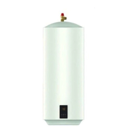
Overview Thank you for purchasing a Superflow series unvented electric water heater. The Superflow is suitable for hand washing and dishwashing where a number of hot outlets are required such as kitchens, schools, restaurants, washrooms and offices. The Superflow is the ideal solution for industrial, commercial and light domestic hot water requirements. -
Page 3: Important Safety Points
1. Important Safety Points Installation must be undertaken by a competent installer of unvented water heating systems in accordance with building regulations G3. Building regulations G3 require a temperature and pressure relief valve to be factory fitted. This must not be removed or blocked in any way. Installation must comply with the latest edition of the IET wiring regulations. - Page 4 Installation Diagram 90 L Model SUPERFLOW Expansion Vessel Pressure & Temperature Pressure (Expansion) Relief Valve Relief Valve Balanced Tundish O Take Check Valve Cold Drain Mains In (Waste) Tundish Pressure Service Reducing Valve Valve Drain Drain Cock Diagram 1 (Waste) Installation Diagram 140 L Model SUPERFLOW Pressure &...
-
Page 5: Plumbing Connection
Plumbing Connection Observe the flow direction arrows on fittings. It is important that the ordering of the fittings is correct as per the diagram 1 and 2. Do not remove the factory fitted pressure and temperature relief valve. Do not insert any other valves between the main manifold and heater inlet as it may prevent the safe expansion and discharge of water during heating cycles. - Page 6 Diagram 2 Discharge Pipe Connection This product falls within the scope of Building Regulation G3 which stipulates certain conditions relating to the way any water discharge from relief valves is transported away. These conditions are designed to ensure that any discharge will not present a hazard to people or to property and that any discharge is clearly visible so that the underlying cause is likely to be rectified promptly.
- Page 7 • The discharge pipe below the tundish is at least 22mm diameter (i.e. one size larger than the pressure and temperature relief valve outlet). • The discharge pipe should be as straight and as short as is possible and positioned away from electrical components.
-
Page 8: Electrical Connection
Electrical Connection • The heater is supplied pre-wired with the appropriate cable. • The electrical installation should conform to the latest edition of the IET wiring regulations. • Electrical supply should be capable of isolation via a user-accessible double isolation switch rated for 13A supply. Diagram 4... - Page 9 3. Commissioning • Visually confirm all plumbing and electrical connections look sound. • Open any tap connected to the hot side of the unit and then turn on the incoming water supply to the heater. • Allow the unit to fill until water flows smoothly from the open tap for around 1 min to ensure the tank is purged of air and any plumbing related debris.
-
Page 10: Operation
4. Operation The maximum temperature setting of the heater is 65°C, this can be excessively hot for some users. In situations where very young children, the elderly or other vulnerable people are the likely users, then a suitably rated thermostatic mixing valve should be fitted to the hot water outlets as required. - Page 11 Resetting the thermal cut- out If the earthing points are removed always ensure a firm reconnection before re-commissioning of the heater. • If the unit stops heating and the element lamp does not illuminate, an over temperature event may have occurred. The unit is fitted with a manually resettable thermal cut-out.
- Page 12 Safety valve inspection • The pressure & temperature valve and the pressure (expansion) relief valves are important safety features of the heater and should be tested periodically to ensure correct functioning. • To test the valves, twist the caps and check that water flows freely. The tundish will allow for visual confirmation that water is flowing during the test.
- Page 13 Legionella risk advice In order that Legionella risk is kept to a minimum the following advice is given; • The heater should be run at its maximum temperature setting (65°C) and flushed through at regular planned intervals. • The whole system should be drained if long periods of non-use are expected. •...
-
Page 14: Specification
6. Specification SR90 SR140 Model *1 kW available on request Power 3.0 kW (*1.0 kW) 3.0 kW (*1.0 kW) Supply voltage/ frequency 230V ~/50Hz 230V ~/50Hz Current 13A (*5A) 13A (*5A) Capacity 90 L 140 L Maximum supply pressure (to pressure 1.2 MPa (12 bar) 1.2 MPa (12 bar) reducing valve) - Page 15 9. Guarantee This product is covered by a standard parts or replacement warranty for a period of 3 years from the date of purchase. If there is a manufacturing defect within the warranty period we will send spare parts, repair and return the unit or, at our discretion, supply a replacement product. Incorrect installation, frost damage, the consequences of limescale deposits or failure to follow correct operating and maintenance instructions are excluded.
- Page 16 In order to underline the duty to dispose of this equipment separately, the product is marked with a crossed out dustbin. Hyco Manufacturing Ltd Normandy Court Express Way...
Need help?
Do you have a question about the Superflow SR90 and is the answer not in the manual?
Questions and answers