Table of Contents
Advertisement
Quick Links
P/NO : 3828VD0131E
All manuals and user guides at all-guides.com
Dec., 2002
Printed in Korea
e-mail:http://www.LGEservice.com/techsup.html
LCD TV
SERVICE MANUAL
CHASSIS : ML-027A
MODEL : RZ-17LZ10
CAUTION
BEFORE SERVICING THE CHASSIS,
READ THE SAFETY PRECAUTIONS IN THIS MANUAL.
ARC
TV/AV/PC MENU
OK
VOL
PR
/I
ON/OFF
website:http://biz.LGservice.com
Advertisement
Table of Contents

Related Manuals for LG RZ-17LZ10


Summary of Contents for LG RZ-17LZ10
- Page 1 All manuals and user guides at all-guides.com website:http://biz.LGservice.com e-mail:http://www.LGEservice.com/techsup.html LCD TV SERVICE MANUAL CHASSIS : ML-027A MODEL : RZ-17LZ10 CAUTION BEFORE SERVICING THE CHASSIS, READ THE SAFETY PRECAUTIONS IN THIS MANUAL. Dec., 2002 TV/AV/PC MENU ON/OFF P/NO : 3828VD0131E Printed in Korea...
-
Page 2: Table Of Contents
All manuals and user guides at all-guides.com CONTENTS Contents ....................2 Safety Precautions ..................3 Servicing Precautions ................4 Specifications ..................6 Description of Controls ................7 Adjustment Instruction ................10 Troubleshooting ..................13 Block Diagram ..................14 Exploded View ..................16 Exploded View Parts List ...............17 Replacement Parts List ................ -
Page 3: Safety Precautions
All manuals and user guides at all-guides.com SAFETY PRECAUTIONS IMPORT ANT SAFETY NOTICE Many electrical and mechanical parts in this chassis have special safety-related characteristics. These parts are identified by the Schematic Diagram and Replacement Parts List. It is essential that these special safety parts should be replaced with the same components as recommended in this manual to prevent X-RADIATION, Shock, Fire, or other Hazards. -
Page 4: Servicing Precautions
All manuals and user guides at all-guides.com SERVICING PRECAUTIONS CAUTION: Before servicing receivers covered by this service transistors and semiconductor "chip" components. The manual and its supplements and addenda, read and follow the following techniques should be used to help reduce the SAFETY PRECAUTIONS on page 3 of this publication. - Page 5 All manuals and user guides at all-guides.com c. Quickly move the soldering iron tip to the junction of the Fuse and Conventional Resistor component lead and the printed circuit foil, and hold it Removal/Replacement there only until the solder flows onto and around both the 1.
-
Page 6: Specifications
All manuals and user guides at all-guides.com SPECIFICATIONS Note : Specification and others are subject to change without notice for improvement. Receivable Broadcasting system: Feature & Funtion PAL-B/G, D/K, I/I Teletext(TOP/FLOF/LIST 10 page) SECAM-B/G, D/K/L/L’ AV Input : 2(Side and Rear) NTSC M S-AV Input : 1(Rear) Component Input : 1(Rear-option) -
Page 7: Description Of Controls
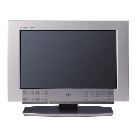
All manuals and user guides at all-guides.com DESCRIPTION OF CONTROLS All the functions can be controlled with the remote control handset. Some functions can also be adjusted with the buttons on the front panel of the set. Only use the remote control handset supplied with this set. If you use other remote control handsets, they’ll not be able to use. - Page 8 All manuals and user guides at all-guides.com 10. TV/PC selects TV or PC monitor mode. clears the menu from the screen. switches the set on from standby. 11. POWER switches the set on from standby or off to standby. 12. I/II selects the language during dual language broadcast.
- Page 9 All manuals and user guides at all-guides.com Front panel TV/AV/PC MENU ON/OFF Side panel 1. ARC 7. REMOTE CONTROL SENSOR select your desired picture format. 8. POWER/STANDBY INDICATOR 2. TV/AV/PC illuminates red when the set is in standby mode. selects TV, AV or PC monitor mode. illuminates green when the set is in power on mode.
-
Page 10: Adjustment Instruction
All manuals and user guides at all-guides.com ADJUSTMENT INSTRUCTION 1. Application Object This instruction is for the application to the LCD TV. 2. Notes (1) This set uses an adapter, so connect the adapter and the set correctly before adjustment. (2) The adjustment must be performed under the correct sequence. - Page 11 All manuals and user guides at all-guides.com 3-3. Position of Mode Adjustment Timing of Mode Table * H[dot]/V[line] SVGA-75 SVGA-85 Mode VGA-60 VGA-67 VGA-75 VGA-85 SVGA-56 SVGA-60 SVGA-72 1056 1048 H_Total 1024 1056 1040 H_Display H_Blanking H_Sync NEG. NEG. H Polarity NEG.
- Page 12 All manuals and user guides at all-guides.com 4. EDID(The Extended Display Identification Data) EDID Table 0B 0C 0D 0E 5. Option1 data Option Code Function Remark Option Code Function Remark 100 Program 200PR Lang. 200 Program Reserved TEXT Off TEXT TEXT On CH.Sound Non Memory 7.
-
Page 13: Troubleshooting
All manuals and user guides at all-guides.com TROUBLESHOOTING 1. General Features Symptom Cause Check Point No screen Input error of inverter connector 1) Bend the pin legs of P1 connector -> recheck them 2) Check and repair the IC804,805. P704 and Pin 21 connector 1) Check and fix P704 connector being slipped out 2) Check and fix the components at P704 LCD module... -
Page 14: Block Diagram
All manuals and user guides at all-guides.com BLOCK DIAGRAM - 14 -... - Page 15 All manuals and user guides at all-guides.com MEMO - 15 -...
-
Page 16: Exploded View
All manuals and user guides at all-guides.com EXPLODED VIEW - 16 -... -
Page 17: Exploded View Parts List
All manuals and user guides at all-guides.com EXPLODED VIEW PARTS LIST PART NO. DESCRIPTION 6304FLP035A LCD MODULE,LM171W01-B3 LG PHILPS TFT COLOR NON 6400GKTX01A SPEAKER,F1527C-6428 K-TONE FULL-RANGE 8OHM 7/12W 83DB 3091V00442A CABINET ASSEMBLY,RZ-17LZ10 NON NON PLATON 5020V00687A BUTTON 5020V00553F BUTTON,POWER RZ-17LZ10 ABS, HF-380 1KEY . -
Page 18: Replacement Parts List
All manuals and user guides at all-guides.com REPLACEMENT PARTS LIST For Capacitor & Resistors, the CC, CX, CK, CN : Ceramic RD : Carbon Film charactors at 2nd and 3rd digit CQ : Polyestor RS : Metal Oxide Film in the P/No. means as follows; CE : Electrolytic RN : Metal Film RF : Fusible... - Page 19 All manuals and user guides at all-guides.com For Capacitor & Resistors, the CC, CX, CK, CN : Ceramic RD : Carbon Film charactors at 2nd and 3rd digit CQ : Polyestor RS : Metal Oxide Film in the P/No. means as follows; CE : Electrolytic RN : Metal Film RF : Fusible...
- Page 20 CONNECTOR ASSY,12P 2.5MM 100MM L205 6210TCE001A 6630VF01810 FILTER,HB-1S2012-080JT CERATEC 2012MM CONNECTOR,YEONHO 10P 1.25MM L206 6210TCE001A FILTER,HB-1S2012-080JT CERATEC 2012MM P1002 6631V25049K CONNECTOR ASSY,4P 2.5MM 300MM L206 6210TCE001A FILTER,HB-1S2012-080JT CERATEC 2012MM P1101A 6602V20005L CONNECTOR,2.0MM 12P GIL-S LG CABLE STRAIGHT - 20 -...
- Page 21 MANUAL,OWNERS ML027A DG/BN LG P602 366-932B CONNECTOR,2.5MM 3P GIL-G LG CABLE S (STICK) 3828VA0366D MANUAL,OWNERS ML027A UK/WTY 366-922C CONNECTOR,2.5MM 4P GIL-G LG CABLE R/A (B TO C) 3828VA0366G MANUAL,OWNERS ML027A ES/PB LG SP/PO P702 366-921L CONNECTOR,2.5MM 12P GIL-G LG CABLE 6710V00091A...
- Page 22 All manuals and user guides at all-guides.com P/No : 3854VA0115A-S(1/2) 2002.11.25...
- Page 23 All manuals and user guides at all-guides.com PRINTED CIRCUIT BOARD MAIN(TOP) MAIN(BOTTOM) USB AUTO(TOP) USB AUTO(BOTTOM) CONTROL P/No : 3854VA0115A-S(2/2) 2002.11.25...
-
Page 24: Svc. Sheet
All manuals and user guides at all-guides.com SVC. SHEET : 3854V A0115A-S...
Need help?
Do you have a question about the RZ-17LZ10 and is the answer not in the manual?
Questions and answers