
Subscribe to Our Youtube Channel
Related Manuals for Salford BBI ENDURANCE


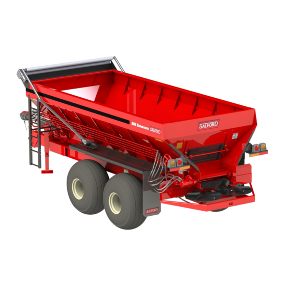
Summary of Contents for Salford BBI ENDURANCE
- Page 1 ENDURANCE OPERATOR’S MANUAL 2019 Salford BBI Inc. 470 South Wayside Street Cornelia, GA 30531 www.salfordgroup.com/bbi-spreaders/ (800) 282-3570 READ MANUAL IN ITS ENTIRETY BEFORE OPERATING MACHINE...
-
Page 2: Table Of Contents
Table of Contents Warranty Information ..........................3 Safety Instructions..........................5 Safety Warnings ..........................6 General Safety ..........................11 Safety Decals ..........................12 Set-up and Preparation..........................Tractor Preparation and Hook-up ....................16 Hydraulic Configuration ........................18 Hydraulic Oil Cooler Information....................20 Pre-Operation Inspection Sheet .....................21 Systems Identification ..........................Binary Manifold ..........................22 Manual Flow Controls -Spinner Speed Adjustment- Conveyor Speed Adjustment ......23 Hydraulic Options- Additional Performance .................24 Operation .............................. -
Page 3: Warranty Information
Salford products are designed and built with longevity and serviceability in mind and are intended to withstand the normal rigors of agricultural use. In case of defect in material or workmanship, Salford Group, Inc. (Salford) will replace and/or repair at its option any part covered by the warranty policy outlined below. - Page 4 Salford offers this warranty work to be done by either the original authorized dealer or a Salford authorized technician. In the case where the work is to be performed by the owner, the reseller will contact Salford BEFORE the work is carried out.
-
Page 5: Safety Instructions
Generally would not involve personal injury. NOTICE! We cannot stress enough the need for personal safety. Salford BBI strongly urges you to make safety your top priority when operating any equipment. Anyone allowed to operate our equipment must be thoroughly trained and tested to prove that they understand the fundamentals for safe operation. - Page 6 12 mph. If road is rough keep speed to minimum, excessive speed may cause machinery to start swerving or tip over. Page 6 07/23/19 Salford BBI Inc.
- Page 7 Absolutely no riders allowed at any time, rider can fall off the implement and get seriously injured or killed. • Do not dismount tractor when tractor is still running. Always engage parking brake before dismounting tractor. Page 7 07/23/19 Salford BBI Inc.
- Page 8 Use transport/maintenance locks when machine is raised. • Maintain proper hydraulic fluid levels. • Keep all connectors clean for positive connections. • Ensure all fittings and hoses are in good condition and are properly tightened. Page 8 07/23/19 Salford BBI Inc.
- Page 9 • Keep all chemicals out of the reach of children and animals. Store in original containers in a locked area. • Dispose of excess chemicals and chemical containers in a proper manner. Page 9 07/23/19 Salford BBI Inc.
- Page 10 Endurance Operator Manual 2019 V1 Safety Instructions Maintenance Safety SALFORD implements are exposed to many types of forces during normal operation. Vibration and friction are two key items that contribute to down-time, therefore it is very IMPORTANT to keep all nuts and bolts tight and all other fasteners (hair pins, linch pins, cotter pins, roll pins etc.) in good...
-
Page 11: General Safety
Be aware of the dangers of hydraulic systems. Hydraulic fluid is under very high pressure, and may cause serious injury if it hits the facial area, especially the eyes. Shut down the entire system before checking hydraulic fluid level or adding fluid to the system. Page 11 07/23/19 Salford BBI Inc. -
Page 12: Safety Decals
2. Replace safety decals and signs that are missing or have become illegible. 3. Replaced parts that displayed a safety sign should also display the current safety sign. 4. Safety Decals are available from your local Salford BBI dealer’s Parts Department or our factory at Salford BBI. - Page 13 Safety Decals (1 of 3) ITEM PART NO. DESCRIPTION ITEM PART NO. DESCRIPTION 10058038 Thrown Object Hazard 10002989 Moving Parts Hazard 10073807 Sever Hazard 10058039 Drag Chain Hazard 10016859 High Pressure Fluid Hazard 2 Page 13 07/23/19 Salford BBI Inc.
- Page 14 Safety Decals (2 of 3) 10076993 6-Bolt Tire Pressure 10074233 8-Bolt Tire Pressure 10076630 10-Bolt Tire Pressure 10073810 Max Payload 10 Tons 10073811 Max Payload 14 Tons 10073808 Max Tow Speed 12 MPH 1 Page 14 07/23/19 Salford BBI Inc.
- Page 15 Endurance Operator Manual 2019 V1 Safety Instructions Safety Decals (3 of 3) 10077468 Max Flow 7 GPM, Large 1 10077467 Max Flow 7 GPM, Small 1 Page 15 07/23/19 Salford BBI Inc.
-
Page 16: Set-Up And Preparation
Check to be sure that no loose parts or other material are in the hopper, on the conveyor or on the spinners. Be sure to remove any loose pieces and ensure all guards are in place. Page 16 07/23/19 Salford BBI Inc. - Page 17 Endurance Operator Manual 2019 V1 Set-up and Preparation Hopper Access Outside Step Locations Never enter the hopper unless another person is present and the tractor is DANGER! shut off! Page 17 07/23/19 Salford BBI Inc.
-
Page 18: Hydraulic Configuration
Mismatched hoses or return hoses that are not properly connected will cause damage to hydraulic components on the spreader. Page 18 07/23/19 Salford BBI Inc. - Page 19 2. Spinner Return (Red-Grey) & Conveyor Return (Blue-Grey) 3. Conveyor Pressure (Blue) 4. Spinner Pressure (Red) NOTE: Failure to follow proper connection procedures before operation could result in damaged equipment and VOID THE WARRANTY. Page 19 07/23/19 Salford BBI Inc.
-
Page 20: Hydraulic Oil Cooler Information
1/4 revolution. Failure to adjust this properly will result in motor seal failure and will void the warranty on the motor. Page 20 07/23/19 Salford BBI Inc. -
Page 21: Pre-Operation Inspection Sheet
Check that the proper hitch pin is torqued properly (refer to used to connect machine to tractor maintenance section) • If transporting long distances and the machine has ground drive, ensure lockout is engaged Notes: Page 21 07/23/19 Salford BBI Inc. -
Page 22: Systems Identification
Systems Identification Binary Manifold™ Salford BBI’s proprietary Binary Manifold™ controls the hydraulic functions of your spreader. The Binary Manifold™ includes modular components for relief, flow control for both the conveyor and spinner circuits and a dump valve used in manual operation. A pressure gauge has also been installed at the factory. -
Page 23: Manual Flow Controls -Spinner Speed Adjustment- Conveyor Speed Adjustment
Note: Even with the Dump Valve ON, the conveyor could still slowly creep when not loaded with material. Disengage the PTO to completely shut off power to the conveyor. Page 23 07/23/19 Salford BBI Inc. -
Page 24: Hydraulic Options- Additional Performance
**In manual operation (no rate controller), the chain speed will double as the High setting is engaged. Proper calibration should be performed to account for this or the application rate will not match the desired rate. Page 24 07/23/19 Salford BBI Inc. -
Page 25: Manual Operation-Setting Application Rate (No Rate Controller)
CALIBRATION- Manual Control (No Rate Controller) Always test and calibrate your spreader prior to operating in the field. Salford BBI, Inc. will not be liable for misapplication due to an uncalibrated applicator. With some limitations, you can achieve relatively accurate application rates using the manual controls. -
Page 26: Rate Chart For Manual Operation
If You Decrease Swath Width To: If You Increase Swath Width To: 35 Ft. Lower Gate 12.5% 45 Ft. Raise Gate 12.5% 30 Ft. Lower Gate 25% 50 Ft. Raise Gate 25% 25 Ft. Lower Gate 37.5% Page 26 07/23/19 Salford BBI Inc. -
Page 27: Factors Affecting Spread Patterns
Because product characteristics will change with each material spread, a certain amount of your own experience with both equipment and material, along with some testing on your part, will determine the adjustments needed to obtain the desired swath width and spread rate. Page 27 07/23/19 Salford BBI Inc. -
Page 28: Pattern Adjustment-Flow Divider
MORE BEHIND SPREADER MORE TO THE SIDES Materials need customer-specific adaptation to suit regional variations. Please be sure to check your pattern when changes to product characteristics are observed. Example: wet vs. dry Page 28 07/23/19 Salford BBI Inc. -
Page 29: Pattern Adjustment-Spinner Speed
Spinner fins will wear and disfigure from the abrasiveness of the materials. Excessive wear can cause an uneven spread pattern. You should replace worn fins before they affect the spread pattern fins are available for purchase from your nearest Salford BBI dealer. Fins PART NO. -
Page 30: Teejet Cl250
0345-05762 Belt Belt 0316-05000 without BBI Binary Repl ac ement cabl e Sensor Manifold Be lt 0316-05000 Sensor Sp inner 0345-05694 Spinner Cable (Optional) 0335-05013 cartridge w/Kit 0390-02558 for spreaders with BBI Binary Manifold Page 30 07/23/19 Salford BBI Inc. -
Page 31: Teejet Ic-18
IC-18 Control System Part Numbers Item Part Number Description Quantity 0378-08063 IC-18 Module 0345-09017 ISObus Cable 0345-05762 Belt Cable 0316-05000 Speed Sensor 0316-05694 Spinner Cable-OPT. 0335-05013 30 GPM Servo Valve 0345-10116 IC-18 to Servo Cable Page 31 07/23/19 Salford BBI Inc. -
Page 32: Controller Setup Information
Next, divide your conveyor sensor pulse count by the CFR. This will yield the spreader constant for the respective gate height. **A new constant will need to be calculated each and every time the gate height is changed. Page 32 07/23/19 Salford BBI Inc. -
Page 33: Lubrication And Maintenance
Wheel Hubs 100 hours Note: Salford BBI has filled Gearboxes with 90-weight oil at the factory. You should replace the factory oil after the first 50 hours of break-in time. Thereafter, you should drain and refill the oil after every season. - Page 34 170 ft/lbs. For 6-bolt hubs, tighten lug nuts to 120 ft/lbs. More information can be found in the appendix about proper tightening procedures. IMPORTANT! Tightening lug nuts more than recommended can damage wheels. Page 34 07/23/19 Salford BBI Inc.
-
Page 35: Hydraulic Maintenance
Overheated oil can cause damage to the hydraulic system, shortening the life of pumps, motors, and other components. High Duty cycle optioned units will have an oil cooler installed. Normal operating temperatures will be in the 135 -145 F degree range. Page 35 07/23/19 Salford BBI Inc. -
Page 36: Adjustments And Service
MAKE SURE THE CHAIN IS ADJUSTED EQUALLY ON BOTH SIDES • A CHAIN TOO LOOSE WILL WRAP AND CATCH OBJECTS • A CHAIN TOO TIGHT WILL STRETCH THE CHAIN BEYOND OPERATING TENSION ADJUSTING Front Roller Adjustment used to change chain tension. Page 36 07/23/19 Salford BBI Inc. - Page 37 NOTE: Conveyor Chain will stretch when first used. Chain must be checked for appropriate tension and properly adjusted to avoid damaging unit. After initial break in period stretching should be minimal. PROPERLY ADJUSTED CHAIN TENSION CHAIN TENSION IS TOO LOOSE CHAIN TENSION IS TOO TIGHT Page 37 07/23/19 Salford BBI Inc.
-
Page 38: Gear Case
90W oil. The shaft seal (part #70601350) is easily damaged by this procedure. Remove and replace with caution. To separate the gear case from the rear roller shaft, remove the bolt from the retaining bracket. Page 38 07/23/19 Salford BBI Inc. -
Page 39: Troubleshooting
Should you encounter problems with your applicator, the following sections list the possible causes and recommended solutions. If the problem persists even after taking the steps recommended in this section, call your Salford dealer. Before you call, have this operator’s manual and the applicator serial number ready. -
Page 40: Parts And Assembly Diagrams
You have several options when needing replacement parts: 1) Phone your local Salford BBI Dealer 2). Contact Salford BBI for assistance in locating dealer and to double check the required part. Visit www.bbispreaders.com and look up your local dealer with the Dealer Locator Tab. - Page 41 Hitch Bracket 24PPI301V3 Perfect Hitch Pintle 24PPI208VR Perfect Hitch Clevis 3/4” Hex Bolt x 5-1/2” 3/4” Nylock Nut 1” Hex Bolt x 7” 1” Nylock Nut 9. Spreader Jack PART NO. DESCRIPTION 24182400 10k Jack Page 41 07/23/19 Salford BBI Inc.
- Page 42 1 3/8” 21 Spline constant velocity 64PTOS61000CV21 64PT150990 Splined 42CRMO4 1.375 x 9.75 Shaft 1 61706B012012 #6 1 3/8” 21 Spline U-Joint 30P360L-P-2012P Permco 360 Pump (2” x 1 1/4”) 15PTO-H360 P360 Pump Guard Page 42 07/23/19 Salford BBI Inc.
- Page 43 Remote Mount Pump (2 1/2” x 2 1/2”) 15PTO-H2A Shaft Guard PTO Shafts- Not Depicted 64PTOS61000CV20 1 3/4” 20 Spline constant velocity PTO **Double check length before ordering as this shaft length has changed. Newer units will utilize the 11.5” shaft. Page 43 07/23/19 Salford BBI Inc.
- Page 44 Pressure Gauge 32GRVCOIL 32 GRV Coil 32GRVCARTRIDGE 32 GRV Cartridge 32ICBVDVS Dump Coil 32ICBVDVC Cartridge 32J1A125WN Spinner Flow Control 32J06A2WN Chain Flow Control 32RAH101530 Spinner Relief Valve 32A04H3HZN Conveyor Relief Valve 0335-05013 Servo Valve Page 44 07/23/19 Salford BBI Inc.
- Page 45 Endurance Operator Manual 2019 V1 Assembly and Part Identification D: Hydraulic Reservoir Components ITEM PART NO. DESCRIPTION 37HTP40 Tank 34HC12012A Breather Cap 34707782A Filter Head 34702784 Filter 34HSG-55 Sight Gauge 32BV-125 Ball Valve Page 45 07/23/19 Salford BBI Inc.
- Page 46 Front Roller 6 Tooth 88K ITEM PART NO. DESCRIPTION 60UCF208-24 1 1/2” Flange Bearing 48FRAA-A Front Roller Adjuster Guide 10055195 Front Roller Adjuster Rod Bracket 2 42FRASS Front Roller Adjuster Rod 10007456 3/4” Nut Page 46 07/23/19 Salford BBI Inc.
- Page 47 2” Flange Bearing 89PSS-20 Flange Bearing Backing *Note: When ordering chain, please have serial number available. **If the serial number of the applicator is not available, please complete chain order form on page 54. Page 47 07/23/19 Salford BBI Inc.
- Page 48 IF A BBI SERIAL # IS NOT AVAILABLE, THEN PLEASE FILL OUT THE INFORMATION BELOW: E. Distance From Center of Rear Roller to Center of Front Roller: PLEASE PROVIDE SIGNATURE TO VERIFY THE INFORMATION PROVIDED IS CORRECT Page 48 07/23/19 Salford BBI Inc.
- Page 49 Assembly and Part Identification G1: Walking Beam - 10 Ton & 14 Ton See Page 57-58 for Spindle and Hub Components Walking Beam PART NO. DESCRIPTION 21AX-WB10 10 Ton Walking Beam 21AX-WB14 14 Ton Walking Beam Page 49 07/23/19 Salford BBI Inc.
- Page 50 NON BRAKE TORSION FLEX AXLE ASSEMBLIES - 45 Degree ITEM PART NO. DESCRIPTION 21AXBB7700224i 7K Axle Assembly 6 Bolt 21AXBB710118i 10K Axle Assembly 8 Bolt BRAKE EQUIPPED AXLES ITEM PART NO. DESCRIPTION 21AXBB7101302 H 10K Brake Axle Assembly 8 Bolt Page 50 07/23/19 Salford BBI Inc.
- Page 51 Endurance Operator Manual 2019 V1 Assembly and Part Identification F1: 7,000 LB (7K) HUB ASSEMBLY 22AX3160340A (6 BOLT) - NO SPINDLE ITEM PART NO. DESCRIPTION 22AX501349 22AX501310 22AX3160340 22AXB0250195 22AXB0190032 22AX67010 22AX67048 22AX1604 Page 51 07/23/19 Salford BBI Inc.
- Page 52 5/8” x 18-90 Press-in Stud 22AXSTN-629 5/8” x 18-90 Lug Nut 22AX501310 10K Outer Race 22AX501349 10K Outer Bearing 22AXSW-1001 10K Axle Washer 22AXSN-1001 10K Axle Nut 22AX1609 10K Dust Cap 22AXSCP-102 10K Cotter Pin Page 52 07/23/19 Salford BBI Inc.
- Page 53 12K 10 Lug Hub Only 22AXBB13564 12K Press in Stud 22AXBB913571 12K Flanged Nut 22AXBB910332 12K Outer Race 22AXBB910334 12K Outer Bearing 22AXBB913632 12K Axle Washer 22AXBB913571 12K Axle Nut 22AXBB909983 12K Dust Cap 22AXSCP-103 12K Cotter Pin Page 53 07/23/19 Salford BBI Inc.
- Page 54 70601173 Small Output Bearing 70601350 Oil Seal 70611952 Tandem Gearcase Gasket 70617006 Lock Washer 70620041 Capscrew 70601360 Seal for Sensor Plug (Purchase in Key and Plug Kit) Center Fill Plug (Purchase in Key Kit) Page 54 07/23/19 Salford BBI Inc.
- Page 55 Assembly and Part Identification H2: Conveyor Motors Standard Hydraulic System Motor Qty. Part Number Description 31BMPH250H2KP BMPH 250 Conveyor Motor High Duty Cycle Hydraulic System Motor Qty. Part Number Description 31BMER-1-1-60- BMER 160 Conveyor Motor FS-RW-C Page 55 07/23/19 Salford BBI Inc.
- Page 56 Tapered locking Hub 50P 1100 Standard Hydraulic System (for 1” shaft) 50P 1125 High Duty Cycle Hydraulic System (for 1- 1/4” shaft) 50HP1B-CL Disc Mounting Hub (located under Spinner Disc) 52LFD110P Endurance Flow Divider Page 56 07/23/19 Salford BBI Inc.
- Page 57 Seal Kit (exploded diagram on page 64) 31SDM360-0-20 Permco 360 Motor Used on High Duty Cycle Hydraulic System. Seal for 360 Motor Seal 30q-1956-4 Seal Installation Tool Tool required when resealing 2 1/2” Motor Page 57 07/23/19 Salford BBI Inc.
- Page 58 W033-3 Washer 9/16” Hex Head Bolt **Spinner Motor Seal Kit Part Number = 31M2100SK152025. Please note for proper installation, the shaft seal insertion tool is required. **Shaft Seal Insertion Tool Part Number = 30q-1956-4. Page 58 07/23/19 Salford BBI Inc.
- Page 59 Gate Wheel Locking Plate Outer Rod Support 4534 Bolt-On Gate Slide 53GWS-2 Mesh Gate Shaft Pinion 53GATECL 4534 Gate Panel 53GSC 1 X 60 OAL Gate Shaft Gate Pillow Block Bearing Plate 60UCP205-16 UCP205-16 Pillow Block Bearing Page 59 07/23/19 Salford BBI Inc.
- Page 60 Assembly and Part Identification L. Tarp Components ITEM DESCRIPTION Tarp Arm Base Plate Tarp Arm Hub Tarp Arm Assembly Tarp Housing and Motor Tarp For additional assistance or information, please contact your local Salford BBI dealer. Page 60 07/23/19 Salford BBI Inc.
-
Page 61: Appendix
Endurance Operator Manual 2019 V1 Appendix Page 61 07/23/19 Salford BBI Inc. -
Page 62: Pump Pressure And Flow Specifications
High Duty Cycle System Pump: Rated flow = 30 GPM from Section 1 (Front) @ 3000 PSI 20 GPM from Section 2 (Back) @ 3000 PSI **All Pressure and Flow Tests should be performed turning the pump input shaft 1000 RPM Page 62 07/23/19 Salford BBI Inc. -
Page 63: Binary Manifold / Hydraulic Motor Plumbing Information
M2A Conveyor Motor #2 Pressure (bottom port on motor #2) M2B Conveyor Motor #2 Return (top port on motor #2) M3A Spinner Circuit Pressure M3B Spinner Circuit Return (Only used on Tractor Supplied Hydraulic Units) Page 63 07/23/19 Salford BBI Inc. - Page 64 M2A Conveyor Motor #2 Pressure (top port on motor #2 - these ports face the rear of the unit) M2B Conveyor Motor #2 Return (bottom port on motor #2) M3A Spinner Circuit Pressure M3B N/A Page 64 07/23/19 Salford BBI Inc.
-
Page 65: Wheel Torque Specifications
NOTE - Recheck the torque settings of lug nuts/bolts after 10 km (6 miles) and again after 50 km (30 miles). Periodically and at the beginning of each season check the condition and the torque of the lug nuts/bolts. Page 65 07/23/19 Salford BBI Inc. -
Page 66: Tire Size And Inflation Pressure
Do not rely on valve stem for orientation of tires. It may face in or out on different rims. See the Specifications table on page _ for the listed tire options for each Endurance length. Page 66 07/23/19 Salford BBI Inc. -
Page 67: Dimensions And Specifications
Endurance Operator Manual 2019 V1 Dimensions and Specifications Tandem Axle Dimensions Page 67 07/23/19 Salford BBI Inc. - Page 68 71 1/2” 97 1/2” Standard 51 1/2” 77 1/2” 103 1/2” High 57 1/2” 83 1/2” 109 1/2” NOTE: Measurements are rounded approximations and are not exact. Allow an 1-inch tolerance for all given values. Page 68 07/23/19 Salford BBI Inc.
-
Page 69: Specifications
Endurance Operator Manual 2019 V1 Dimensions and Specifications Specifications Page 69 07/23/19 Salford BBI Inc. -
Page 70: Oil Cooler Schematic (High Duty Cycle Option Only)
SHEET SIZE: THIS DRAWING CONTAINS CONFIDENTIAL AND/OR PRIVILEGED INFORMATION. THIS UNLESS NOTED DRAWING AND ANY INFORMATION CONTAINED THEREIN SHALL NOT BE REPRODUCED OR USED IN ANY WAY DETRIMENTAL TO THE INTEREST OF SALFORD GROUP INC. .XXX +/- .005 REV: PART NUMBER:...
Need help?
Do you have a question about the BBI ENDURANCE and is the answer not in the manual?
Questions and answers