
Related Manuals for Finn B260 SEB


Summary of Contents for Finn B260 SEB
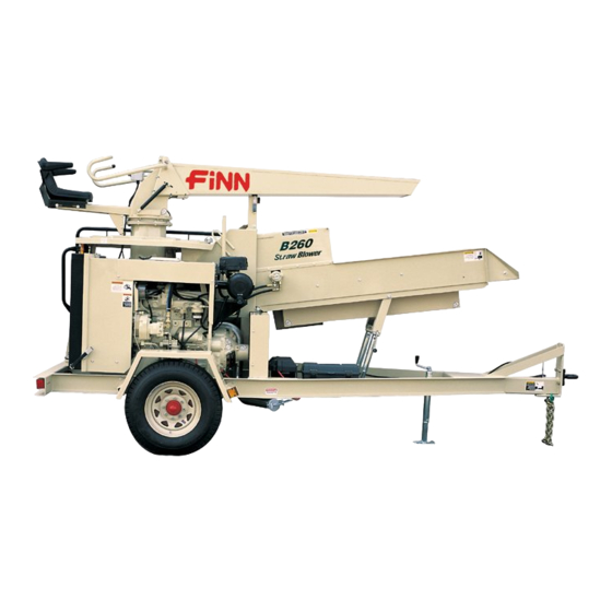
- Page 1 9281 LeSaint Drive • Fairfield, Ohio 45014 Phone (513) 874-2818 • Fax (513) 874-2914 Sales: 1-800-543-7166 B260 Straw Blower Parts and Operator’s Manual Model SEB Serial No. ___________ LBB260-SEB Rev A...
- Page 2 NOTES...
- Page 3 ▪ Return the part(s) and the completed Warranty Claim Form to Finn Corporation using the return shipping label. (Within 2 weeks) ▪ Tape the Orange identifier sheet, marked with the W / RMA# on the outside of the box you are shipping the defective part(s) to Finn in.
- Page 4 (except those referred to herein) that are manufac- dealers, or any other party. tured by Finn to be free from defects in material and workmanship 5. This Warranty does NOT cover any costs associated with trans- for a period of 12 months from date of purchase or 1200 hours of use, whichever comes first.
-
Page 5: Table Of Contents
Definition of Mulching......... 5 The Finn B260 Straw Blower and How It Works ....5 Towing Truck . - Page 6 INDEX CONTINUED Parts Manual Section ........23-58 Notes .
-
Page 7: Safety First
SAFETY FIRST With any piece of equipment, new or used, the most important part of its operation is SAFETY! Finn Corporation encourages you and your employees to familiarize yourselves with your new equipment and to stress safe operation. The first three pages of this manual are a summary of all the main safety aspects associated with this unit. -
Page 8: Safety Summary Section
The FINN STRAW BLOWER is intended to be used as an applicator of vegetative hay or straw mulches onto the seedbed. Its use with other products or for other applications must be by approval of the product's manufacturer. - Page 9 Signal "All Clear" before restarting It is recommended that only authorized genuine the machine. FINN replacement parts be used on the machine. Do not use ether cold start fluid if engine is equipped III. MAINTENANCE: with glow plug type preheater or other intake mani-...
- Page 10 CURRENT SET OF SAFETY DECALS...
-
Page 11: Definition Of Mulching
TOWING TRUCK: The truck used to tow the Finn Straw Blower should have a bed large enough to carry the quantity of mulch needed for economical operation. If the Straw Blower is going to be used on rough, hilly terrain, a truck with a two-speed axle is suggested. -
Page 12: Attachments (50' Extension For Discharge Spout)
The valve on the extension is used the same way as the main valve on your Finn Straw Blower. Since less mulch is being fed into the machine, less asphalt is required and smaller asphalt spray nozzles are used when the spout extension is in place. -
Page 13: Pre-Start Check
PRE-START CHECK: Safety check to insure operator safety: 1. Check the bolts on the hitch and safety chains, the brakes, and the trailer lights. 2. With ignition "On", check the amber safety light. 3. Check the signal horn. 4. Insure that all guards are in place. 5. -
Page 14: Starting The Engine
5. With the engine still idling, engage the clutch slowly. Move the throttle to wide-open position and let the governor control the engine speed. Governed speed of the engine on the Finn Straw Blower should be 2550 to 2600 RPM under load. -
Page 15: Powerview
POWERVIEW The PowerView is a multifunctional tool that enables the operator to view many different engine parameters and service codes. A graphical back-lit LCD screen can display either a single parameter or a quadrant dis- play showing four parameters simultaneously. Diagnostic capabilities include fault codes with text transla- tion for the most common fault conditions. -
Page 16: Powerview Operation
POWERVIEW OPERATION PowerView Menus (First Time Start Up) 1. Once the engine has been started and the 2000 4000 keyswitch is turned to "RUN", the RPM 1800 RPM Engine Parameter is displayed. See Figure 2. ENG RPM COOL TEMP 2. To toggle through the various engine param- eters, touch either the left or right arrow key. - Page 17 4. Once the stored fault codes have been retrieved, the initial code will be displayed along with a text description. See Figure 7. REQUESTING 5. If the word "MORE" appears at the bottom FAULT CODES of the display, this indicates that there are additional fault codes being stored.
-
Page 18: Crew Members And Their Duties
FEEDING THE MULCH: The power feed assembly of the Finn Straw Blower has been designed to give fast, uniform, mechanical feeding. The adjustable feeding rate allows use of varied materials and at the same time obtains maximum production. -
Page 19: Distributing The Mulch
DISTRIBUTING THE MULCH: The Straw Blower should be towed to a point approximately 60' (18 m) from the area where mulch is to be applied. The elevator elevates the discharge spout about 10˚ above the plain of the seedbed so that the mulch floats onto the seedbed. Do not drive the mulch into the seedbed with air pressure. The higher the tube is held, the more uniform the application will be. -
Page 20: Hydraulic System
Grade 46 Hydraulic Oil. Hydraulic oil should be replaced per the lubrication schedule or if the oil becomes milky or gives off a burnt odor. Hydraulic oil filter must be replaced with a 25 Micron absolute filter – Finn part # 021618. The following checks will keep your Finn Straw Blower in proper operating condition: 1. -
Page 21: Trouble Shooting The Hydraulic System
TROUBLE SHOOTING THE HYDRAULIC SYSTEM: Symptom Probable Cause Remedy Power feed motor will Plugged suction strainer. Clean strainer. not run in either direction. Suction line valve closed. Open valve. Collapsed suction hose. Replace hose. Worn pump. Repair or replace. Power feed chain runs Loose chain. -
Page 22: Weekly Maintenance
2. Clean the radiator and radiator screen with tap water. 3. Check crankcase oil level and add oil if necessary. 4. Check the tension on the power band 3/8" (1 cm) depression at the center of the band using 8 lbs. (3.6 kg) of pressure and adjust if necessary. - Page 23 REAR JACKING BOLT FRONT JACKING BOLT TIGHTEN LOOSEN FRONT ENGINE MOUNT APPLY 8 LBS OF PRESSURE REAR ENGINE FOOT HALFWAY BETWEEN SHEAVES RULER STRAIGHT EDGE 3/8” DRIVE BELT ENGINE CLUTCH SHEAVE BLOWER SHAFT SHEAVE FIGURE 8 - ADJUSTING THE DRIVE BELT...
-
Page 24: Adjusting The Feed Chain
ADJUSTING THE FEED CHAIN: 1. About halfway between the Idler Sprocket Assembly and the Drive Shaft Idler Assembly, pull the Feed Chain taut away from the bottom of the Feed Chute Weldment. At the point where you have pulled the Feed Chain away measure the distance between the top of the Feed Chain and the bottom of the Feed Chute Weldment. -
Page 25: Clutch Care And Maintenance
CLUTCH CARE AND MAINTENANCE: This is a short, simple outline of the Twin Disk Clutch adjustment and lubrication procedures. When per- forming maintenance beyond this brief outline, refer to the Twin Disk Clutch Care and Operations Manual. In order to properly identify parts when ordering replacement parts, always refer to the unit and specification number stamped on the name plate on the top center of the power take-off housing. - Page 26 HYDRAULIC OIL LEVEL AND FILTER POWER FEED SHAFT BEARINGS POWER SYSTEM BLOWER SHAFT BEARINGS...
-
Page 27: Lubrication Chart
LUBRICATION CHART Ref. No. Location Lubricant Frequency Number Clutch Shaft Bearing Weekly Check Engine Oil Level Daily Clutch Yoke Shaft Weekly Check Air Cleaner Daily Check Hydraulic Oil Level Daily Change Hydraulic Oil and Filter Annually Discharge Elbow Bearing Daily Rotate Elbow to 6 or 8 different positions Power Feed Shaft Bearings Weekly... -
Page 28: Notes
NOTES... - Page 29 B260 Straw Blower Parts Manual Model SEB...
- Page 30 NOTES...
- Page 31 FINN B260 STRAW BLOWER FEED CHUTE See Pages 48-51 OPERATOR PLATFORM AND DISCHARGE HEAD See Pages 52-57 SHREDDER & BLOWER See Pages 30-33 POWER SYSTEM See Pages 34-47 TRAILER See Pages 26-29 See Pages 58-59 DECAL LOCATIONS See Page 60...
- Page 32 REF: TRAILER WIRING (SEE PAGE 29) REF: AXLE ASSEMBLY (SEE PAGE 28) WHEN ORDERING PARTS, BE SURE TO STATE SERIAL NUMBER OF MACHINE...
-
Page 33: Trailer
TRAILER Ref. No. Part Number Description No. Req’d 080043 Tow Ring (Standard) 005134 Coupler (Optional) 005135 2-5/16" Ball (Optional) 190033 Safety Chain - 3' Length 004888 Coupling Link 023485 Clevis Grab Hook 022588 Frame Jack 023592 Dual Jack Mount 023654 Dual Jack Arrangement 023637 Jack With Stub Shaft... -
Page 34: Axle Assembly
*NOTE: ITEM #6 ALSO INCLUDES ITEM #7. AXLE ASSEMBLY Ref. No. Part Number Description No. Req’d 023741 Axle with Spindles, Hubs and Drums 080669 Wheel and Tire Assembly 080668 Tire 1 per 023780 Tire Valve 1 per 080663 Wheel WL8-219-4 Hub and Drum Assembly WL6-80 Wheel Nut... -
Page 35: Trailer Wiring
TRAILER PLUG TAIL LIGHTS (BROWN) NOT USED 16 GA. (RED) TO STARTER 16 GA. (YELLOW) TO LEFT TAILLIGHT LEFT RIGHT TURN TURN 16 GA. (GREEN) TO RIGHT TAILLIGHT (YELLOW) (GREEN) 16 GA. (WHITE) TO BRAKE GROUND ELECTRIC BRAKES (WHITE) (BLACK) 16 GA. -
Page 36: Beater Chain Assemblies
REF: BEATER CHAIN ASSEMBLIES (SEE PAGES 32-33) WHEN ORDERING PARTS, BE SURE TO STATE SERIAL NUMBER OF MACHINE... - Page 37 SHREDDER BOX & BLOWER HOUSING Ref. No. Part Number Description No. Req’d 023418 Blower Shaft End Cover 021511 Bearing 023632 Blower Cover Weldment 023311 Blower Blade Assembly 021512 Bushing 022159 021361* Beater Chain Assembly - 3 Pitch 021822* Beater Chain Assembly - 4 Pitch 023228* Beater Chain Assembly - 5 Pitch 023334...
- Page 38 ITEM #1 (3-PITCH BEATER CHAIN ASSEMBLY) INCLUDES ITEMS #2 - 6. ITEM #7 (4-PITCH BEATER CHAIN ASSEMBLY) INCLUDES ITEMS #8 - 12. 4-PITCH BEATER CHAIN ASSEMBLY ITEM #13 (5-PITCH BEATER CHAIN ASSEMBLY) INCLUDES ITEMS #14 - 18. WHEN ORDERING PARTS, BE SURE TO STATE SERIAL NUMBER OF MACHINE...
- Page 39 BEATER CHAIN ASSEMBLIES Ref. No. Part Number Description No. Req’d 021361 Beater Chain Assembly - 3-Pitch 020111 Chain - 3-Pitch 022487 020119 Chain Pin 021363 Bushing 021555 Beater Hub Weldment 021822 Beater Chain Assembly - 4-Pitch 020110 Chain - 4-Pitch 022487 020119 Chain Pin...
- Page 40 REF: AIR INTAKE & EXHAUST SYSTEM (SEE PAGES 42-43) REF: ENGINE & RADIATOR (SEE PAGES 36-37) WHEN ORDERING PARTS, BE SURE TO STATE SERIAL NUMBER OF MACHINE...
-
Page 41: Power System
POWER SYSTEM Ref. No. Part Number Description No. Req’d 052398-08 Rear Engine Spacer 006499* Horn 023847 Air Cleaner Bracket F260-0025 Engine Plug Bracket JDR517320 Engine Wiring Harness F260-0023 Rear Engine Panel F260-0006-03 Hinge Spacer F260-0006-02 Radiator Cap Cover 055669 Position Locking Hinge F260-0022 Engine Side Panel F260-0021... - Page 42 REF: POWER TAKE-OFF ASSEMBLY (SEE PAGES 38-39) WHEN ORDERING PARTS, BE SURE TO STATE SERIAL NUMBER OF MACHINE...
-
Page 43: Engine And Radiator
ENGINE AND RADIATOR Ref. No. Part Number Description No. Req’d 023864 4045T Tier 2 Engine Assembly JDRE509031 Fuel Filter JDRE517181 Water Separator 023539 Rear Engine Foot 023166 Rear Jacking Bolt 023167 Front Jacking Bolt 023846 Front Engine Mount F260-0009 Air Deflector JDRE504836 Oil Filter 023685... - Page 44 28 29 30 31 NOTES: ITEM #1 (POWER TAKE-OFF ASSEMBLY) INCLUDES ITEMS #2 - 51. ITEM #2 (CLUTCH ASSEMBLY) INCLUDES ITEMS #3 - 23. TWIN DISK CLUTCH SHOWN. SEE NOTE ON PAGE 39 FOR ADDITIONAL INFORMATION. WHEN ORDERING PARTS, BE SURE TO STATE SERIAL NUMBER OF MACHINE...
-
Page 45: Power Take-Off Assembly
Adjusting Lock Pin Spring Finger Pin Adjusting Yoke IMPORTANT Finger Lever Cotter Pin Sliding Sleeve Assembly FINN B260 Straw Blowers have Lever Link Pin been provided with NACD & Twin Lever Link Disk Clutch Assemblies. Refer to Cotter Pin FINN Technical Bulletin #2005-... - Page 46 WHEN ORDERING PARTS, BE SURE TO STATE SERIAL NUMBER OF MACHINE...
-
Page 47: Hydraulic System
HYDRAULIC SYSTEM Ref. No. Part Number Description No. Req’d 004900 Filler Breather Cap 011466 Suction Strainer 160305 Close Nipple 021559 Ball Valve 023809 Suction Hose 023620 90 Degree A dapter Elbow 023685 Hydraulic Pump 055359 Straight Adapter 023810 Pressure Hose 023617 Straight Adapter 011625... - Page 48 ITEM #2 (AIR CLEANER ASSEMBLY) INCLUDES ITEMS #3 - #6 ITEM #1 (AIR INTAKE ASSEMBLY) INCLUDES ITEMS #2 - #17 ITEM #6 (AIR CLEANER) INCLUDES ITEMS #7 - #12 TURBO ENGINE ASSEMBLY (SEE PAGES 36-37) ITEM #18 (EXHAUST ASSEMBLY) INCLUDES ITEMS #19 - #25 WHEN ORDERING PARTS, BE SURE TO STATE SERIAL NUMBER OF MACHINE...
- Page 49 AIR INTAKE & EXHAUST SYSTEM Ref. No. Part Number Description No. Req’d 023848 Air Intake Assembly 012646 Air Cleaner & Pre-Cleaner Assembly 012608 Pre-Cleaner 022657 4" Clamp 012609 Pre-Cleaner Adapter 012621 Air Cleaner 012621B Dust Load Indicator Gauge 012621C Spring-Loaded Mount 012623 Safety Filter Element (3.75-E2) 012622...
- Page 50 (White) PILOT LIGHT (Yellow) (White) (Blue) (White) (Green) (Black) HORN BUTTON 87A 30 (Black) (Black) (Red) 2-CONDUCTOR (Brown) CABLE (Strip Back 3”) (Black) HORN THROTTLE EMULATOR WHEN ORDERING PARTS, BE SURE TO STATE SERIAL NUMBER OF MACHINE...
-
Page 51: Control Box Wiring Diagram
CONTROL BOX WIRING DIAGRAM Part Number Description No. Req’d 023868 Tier II Control Box Cable Assembly FW71555 Toggle Switch 080526 Switch Boot 052076 Key Switch 023076 Key For Ignition Switch 023869 Modified Control Box 012739 PowerView 006245 Pilot Light 022425 Diode FW71749-02 30 Amp Relay... - Page 52 SAFETY SWITCHES DOOR E-STOP SWITCH SWITCH DOOR SWITCH (Black) (White) (White) (White) (White) (Black) (Black) E-STOP SWITCH ENGINE CONNNECTIONS WIRES FROM FLASHING DEERE HARNESS LIGHT TERMINAL RAIL (Black) (Green) STARTER RELAY (Black) Battery Cable STARTER (Black) (Red) FROM CONTROL CABLE ALTERNATOR (Orange) From Deere Harness...
-
Page 53: Engine Wiring Diagram
ENGINE WIRING DIAGRAM Part Number Description No. Req’d 023862 E-Stop and Enclosure* 052436 Door Switch** 011851 Battery*** 000241 Ground Strap 080096 Battery Cable*** 007336 Amber Flashing Light**** 021198 Flasher 075522 1-1/4" Dia Loop Clamp 022891 Starter Relay 031401 Stud Type Junction Block - 8 Std NOTES: See Pages 48-49 for Location See Pages 30-31 and 52-53 for Location... - Page 54 REF: FEEDER ROLL ASSEMBLY (SEE PAGES 50-51) WHEN ORDERING PARTS, BE SURE TO STATE SERIAL NUMBER OF MACHINE...
-
Page 55: Feed Chute Assembly
FEED CHUTE ASSEMBLY Ref. No. Part Number Description No. Req’d 023542 Feed Chute Extension 023570 Feed Chute Weldment 023590 Feed Chain Guard 023361 Drive Chain Guard 023153 Drive Chain X12112 Hinge Bolt 023171-01 Feed Chute Cover 023348-02 Air Baffle Door Rod F260-0016 Air Baffle Door 023158-02... - Page 56 ITEM #1 REF: (FEEDER ROLL ASSEMBLY) FEED CHUTE INCLUDES ITEMS #2 - #13. WELDMENT (SEE PAGES 48-49) WHEN ORDERING PARTS, BE SURE TO STATE SERIAL NUMBER OF MACHINE...
-
Page 57: Feeder Roll Assembly
FEEDER ROLL ASSEMBLY Ref. No. Part Number Description No. Req’d 023189 Feeder Roll Assembly 023596 Drive Sprocket 020586 Flange Bearing 023125 Feeder Roll End Cap - Bearing Side 023123 Feeder Roll Weldment 023152 Feeder Roll End Cap - Motor Side 023249 023190 Feeder Roll Drive Shaft... - Page 58 REF: SEAT ASSEMBLY GAS SPRING DETAIL (SEE PAGES 56-57) DISCHARGE HEAD (SEE PAGES 54-55) WHEN ORDERING PARTS, BE SURE TO STATE SERIAL NUMBER OF MACHINE...
-
Page 59: Operator Platform
OPERATOR PLATFORM Ref. No. Part Number Description No. Req’d 023626 Lower Transition 023633-02 Rotary Stop 052436 Door Switch* 052707 Hex Nut 023689 Clamp 023690 Strike 023688 Access Door 007336 Amber Flashing Light* 023638-03 Hand Rail 023551 Ladder 023549 Platform 023638 Guard Rail 023836 Kick Strap Assembly... - Page 60 REF: CONTROL BOX (SEE PAGES 44-45) REF: SEAT ASSEMBLY FLAPPER SEAL (SEE PAGES 56-57) DOOR DETAIL (PAGE 55) WHEN ORDERING PARTS, BE SURE TO STATE SERIAL NUMBER OF MACHINE...
-
Page 61: Discharge Head
FLAPPER SEAL DOOR DETAIL ITEM #14 (FLAPPER DOOR SEAL ASSEMBLY) INCLUDES ITEMS #15 - 20. DISCHARGE HEAD Ref. No. Part Number Description No. Req’d 023629 Discharge Tube 023726-01 Top Seal 023726-04 Top Seal Retainer 023588-01 Handle Weldment - Left Hand Side 004996 Plastic Pipe Plug 023588-02... - Page 62 WHEN ORDERING PARTS, BE SURE TO STATE SERIAL NUMBER OF MACHINE...
-
Page 63: Seat Assembly
SEAT ASSEMBLY Ref. No. Part Number Description No. Req’d 023884 Seat Assembly 023885 Armrest Kit 035024-09 Spacer F260-0026 Seat Mounting Bracket 022202 Black Handle Grip F260-0015 Power Feed Handle 023876 Discharge Elbow Weldment 023639 99" Lg. Push-Pull Control Cable 023555-02 Control Cable Plate Weldment 023554-01 Control Cable Guard... - Page 64 NOTE: ITEM #5 (DECAL KIT) INCLUDES ITEMS #6-29 DIESEL FUEL WHEN ORDERING PARTS, BE SURE TO STATE SERIAL NUMBER OF MACHINE...
-
Page 65: Decal Locations
DECAL LOCATIONS Ref. No. Part Number Description No. Req’d 023174 Decal "FINN" 023856-01 Decal "B260" 023855 Decal "Straw Blower" 011690 FINN Nameplate 023881 Decal Kit 022690 Decal "WARNING! Flying Objects!" 007231 Decal "Service Weekly" 023877 Decal "Throttle" 023880 Decal "Safety Switches KL2411303 Decal "Ignition"... - Page 66 021375 Grease Gun 021741 Grease Gun Hose 020365 Grease Cartridge 012681A Touch-Up Paint (FINN Beige - 4.5 oz. Aerosol) 012681T Touch-Up Paint (FINN Beige - 0.5 oz. Wet) 020057 Twine Cutter (Size #13) 020063 Twine Cutter (Size #11) Engine Operation and Maintenance Manual...
-
Page 67: Notes
NOTES...
Need help?
Do you have a question about the B260 SEB and is the answer not in the manual?
Questions and answers