Table of Contents
Advertisement
Quick Links
Operator Instructions and Parts Manual
B260 MN0224
9281 LeSaint Drive • Fairfield, Ohio 45014
Phone (513) 874-2818 • Fax (513) 874-2914
Sales: 1-800-543-7166
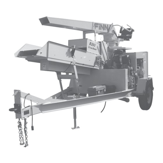
B260 Straw Blower
Model MN
Serial No. _____________
Activate
Activate
Your Warranty
Your Warranty
By Registering
By Registering
TODAY!!!
TODAY!!!
Advertisement
Table of Contents

Subscribe to Our Youtube Channel
Related Manuals for Finn B260


Summary of Contents for Finn B260
- Page 1 Your Warranty Your Warranty By Registering By Registering TODAY!!! TODAY!!! 9281 LeSaint Drive • Fairfield, Ohio 45014 Phone (513) 874-2818 • Fax (513) 874-2914 Sales: 1-800-543-7166 B260 Straw Blower Operator Instructions and Parts Manual Model MN Serial No. _____________ B260 MN0224...
- Page 3 IF FINN CORPORATION DOES NOT HAVE YOUR COMPLETED REGISTRATION FORM ON FILE, YOUR WARRANTY CLAIM WILL BE DENIED. Once your FINN equipment has been registered, your FINN Limited Warranty will be activated per the warranty statement on the next page.
-
Page 5: Table Of Contents
Definition of Mulching ..........5 The FINN B260 Straw Blower and How It Works......5 Towing Vehicle . - Page 6 INDEX Parts Manual Section ..........23 - 60 Trailer.
-
Page 7: Safety First
SAFETY FIRST With any piece of equipment, new or used, the most important part of its operation is SAFETY! FINN Corporation encourages you and your employees to familiarize yourselves with your new equipment and stresses safe operation. The first five pages of this manual are a summary of the main safety aspects associated with this unit. -
Page 8: Straw Blower Safety Summary Section
The FINN STRAW BLOWER is intended to be used as an applicator of vegetative hay or straw mulches onto the seedbed. Its use with other products or for other applications must be by approval of the product’s manufacturer. - Page 9 Use lockout/tagout procedure [Occupational Health and 5. It is recommended that only authorized, Safety Administration (OSHA) genuine FINN replacement parts be used on 29 CFR 1910.147]. the machine. 6. Make certain that all decals on the machine are maintained in good legible condition.
-
Page 10: Common Safety Decals
COMMON SAFETY DECALS... -
Page 11: Introduction
THE FINN B260 STRAW BLOWER AND HOW IT WORKS The FINN B260 Straw Blower will apply vegetative mulch at a fast and uniform rate, utilizing a minimum amount of manpower. The baled vegetative mulch material is placed on the feed chute and separated by the bale feeder as the bales are fed into the shredder housing. -
Page 12: Attachment (50 Ft Extension For Discharge Spout)
ATTACHMENT: 50 ft. (15 m) EXTENSION FOR DISCHARGE SPOUT The collapsible tube, when secured to the spout of the adapter, will extend the length of the discharge spout by 50 ft (15 m). When this tube is attached, mulch material must be pushed farther through the tube before being discharged. -
Page 13: Equipment Check
EQUIPMENT CHECK Equipment check should be made with the engine OFF and all rotating parts stopped. Failure to comply could result in death or serious injury. 1. Make sure the tool kit contains all prescribed items (see tool kit list in the parts section of this manual). -
Page 14: Starting The Engine
5. With the engine still idling, engage the clutch slowly. Move the throttle to the wide-open position and let the governor control the engine speed. The governed speed of the engine on the FINN Straw Blower should be 2,550 to 2,600 RPM under a load. Before engaging the clutch, make sure that the discharge chute is under control and is pointed in the proper direction. -
Page 15: Powerview
POWERVIEW The PowerView is a multifunctional tool that enables the operator to view many different engine parameters and service codes. A graphical back-lit LCD screen can display either a single parameter or a quadrant display showing four parameters simultaneously. Diagnostic capabilities include fault codes with text translation for the most common fault conditions. -
Page 16: Powerview Operation
POWERVIEW OPERATION PowerView Menus (First Time Start-Up) 1. Once the engine has been started and the keyswitch is turned to RUN, the Engine RPM parameter (ENG RPM) is displayed. See 2000 4000 1800 RPM Figure 2. 2. To toggle through the various engine ENG RPM COOL TEMP parameters, touch either the Left or Right... -
Page 17: Crew Members And Their Duties
4. Once the stored fault codes have been retrieved, the initial code will be displayed along with a text description. See Figure 7. REQUESTING FAULT CODES 5. If the word MORE appears at the bottom of the display, this indicates that there are additional fault codes being stored. -
Page 18: Feeding The Mulch
FEEDING THE MULCH The power feed assembly of the FINN Straw Blower has been designed to give fast, uniform mechanical feeding. The adjustable feeding rate allows the use of various materials, and at the same time obtains maximum production.The power feed assembly is driven by a power feed chain.This allows the mulch material to be fed at an adjustable rate to the separator roll, which... -
Page 19: Smoothing Out Mulch Patterns
SMOOTHING OUT MULCH PATTERNS The lower roll assembly in the shredder housing, driven by the blower power band, is equipped with mounting points for eight beater chains and six fingers. For normal straw application, only four to six chains are needed. If you have material coming out in lumps or find it impossible to handle because the mulch is wet or hard, install extra chains in pairs until smoothness of mulch application is reached. -
Page 20: Hydraulic System
The hydraulic-system oil filter cartridge must be replaced with a 5 Micron absolute filter cartridge (FINN part number 023914). The following checks will keep your FINN Straw Blower in proper operating condition: 1. -
Page 21: Cleaning And Maintenance
CLEANING AND MAINTENANCE Before servicing the machine, turn off engine and allow all moving parts to stop. Disconnect the battery cables to prevent accidental starting of the machine. Tag the engine operating area to show that the machine is being serviced. Use lockout/ tagout procedure (29 CFR 1910.147). -
Page 22: Adjusting The Drive Belt
CLEANING AND MAINTENANCE (CONTINUED) ADJUSTING THE DRIVE BELT 1. Remove the BELT GUARD to expose the DRIVE BELT. 2. Position a straight edge across the belt, starting from the BLOWER SHAFT SHEAVE and extending across the top of the ENGINE CLUTCH SHEAVE (see Figure 8). 3. - Page 23 REAR JACKING BOLT FRONT JACKING BOLT TIGHTEN LOOSEN FRONT ENGINE MOUNT REAR ENGINE FOOT APPLY 8 LBS OF PRESSURE HALFWAY BETWEEN SHEAVES RULER STRAIGHT EDGE 3/8 inch DRIVE BELT ENGINE CLUTCH SHEAVE BLOWER SHAFT SHEAVE Figure 8 - Adjusting the Drive Belt...
-
Page 24: Adjusting The Feed Chain
ADJUSTING THE FEED CHAIN 1. About halfway between the IDLER SPROCKET ASSEMBLY and the DRIVE SHAFT IDLER ASSEMBLY, pull the FEED CHAIN taut and away from the bottom of the FEED CHUTE WELDMENT. At the point where you have pulled the FEED CHAIN away, measure the distance between the top of the FEED CHAIN and the bottom of the FEED CHUTE WELDMENT. -
Page 25: Clutch Care And Maintenance
CLUTCH CARE AND MAINTENANCE This is an outline of the PTO clutch adjustment and lubrication procedure. When you perform maintenance beyond this outline, refer to the power take-off manufacturer's service manual. In order to properly identify parts when ordering replacement parts, always refer to the unit and specification number stamped on the nameplate located on the top center of the power take-off housing. - Page 26 HYDRAULIC OIL LEVEL AND FILTER POWER FEED SHAFT BEARINGS POWER SYSTEM BLOWER SHAFT BEARINGS Figure 10 - Lubrication Points...
-
Page 27: Lubrication
LUBRICATION CHART Ref. No. Location Lubricant Frequency Number Clutch Shaft Bearing Daily Check Engine Oil Level Daily Clutch Yoke Shaft Weekly Check Air Cleaner Daily Check Hydraulic Oil Level Daily Discharge Elbow Bearing Daily (Rotate Elbow to eight different positions while applying lubrication.) Power Feed Shaft Bearings Weekly... - Page 28 THIS PAGE LEFT BLANK INTENTIONALLY...
- Page 29 B260 Straw Blower Parts Manual Model MN WHEN ORDERING PARTS, BE SURE TO STATE SERIAL NUMBER OF MACHINE B260 MN0224...
- Page 30 TRAILER WIRING WHEN ORDERING PARTS, BE SURE TO STATE SERIAL NUMBER OF MACHINE B260 MN0224...
-
Page 31: Trailer
License Plate Mounting Bracket 005137 Left Taillight Assembly 005137-A Lens FW71090 Marker Light (Amber) F400-0031 Battery Box Fab 011770 Battery Box F400-0038 Battery Box Hold Down Continued to next page. WHEN ORDERING PARTS, BE SURE TO STATE SERIAL NUMBER OF MACHINE B260 MN0224... - Page 32 1-1/2 ft 005017 Snap Hook 023762 B260 Wiring Harness (Single Axle Trailer Only) 023945 B260 Wiring Harness (Skid and Tandem Trailer Only) 075592 7-Blade Trailer Plug F260-0048 Fender Light Mounting Plate (Tandem Trailer Only) NOT SHOWN Fuel Tank Parts Not Illustrated...
-
Page 33: Axle Assembly
1 per 005830 Wheel Assembly (ST225 / 90D16 on 16 x 6 Rim) 2 per axle 008525-02 Wheel Nut 8 per NOT SHOWN 005811-01 Rubber Plug 1 per WHEN ORDERING PARTS, BE SURE TO STATE SERIAL NUMBER OF MACHINE B260 MN0224... - Page 34 REFER TO BEATER CHAIN ASSEMBLIES WHEN ORDERING PARTS, BE SURE TO STATE SERIAL NUMBER OF MACHINE B260 MN0224...
-
Page 35: Shredder Box And Blower Housing
Elbow 90 Degree ST 1/8 023850 15 in. Lg. Grease Hose 160152 1/8 in. Standard Coupling 007705 1/8 in. NPTF Straight Grease Fitting KITS AND MARKERS See Wiring Diagram Section. WHEN ORDERING PARTS, BE SURE TO STATE SERIAL NUMBER OF MACHINE B260 MN0224... - Page 36 WHEN ORDERING PARTS, BE SURE TO STATE SERIAL NUMBER OF MACHINE B260 MN0224...
-
Page 37: Beater Chain Assemblies
Beater Hub Weldment KITS AND MARKERS 021361 Beater Chain Assembly - 3-Pitch 021822 Beater Chain Assembly - 4-Pitch 023228 Beater Chain Assembly - 5-Pitch WHEN ORDERING PARTS, BE SURE TO STATE SERIAL NUMBER OF MACHINE B260 MN0224... - Page 38 REFER TO AIR INTAKE AND EXHAUST SYSTEM REFER TO ENGINE AND RADIATOR WHEN ORDERING PARTS, BE SURE TO STATE SERIAL NUMBER OF MACHINE B260 MN0224...
-
Page 39: Engine Sheet Metal
Radiator Chaff Screen 190087 Chaff Screen Seal 124 in. 023667 Chaff Screen Latch F260-0042 Radiator Shroud Weldment F260-0042-06 Side Filler Angle KITS AND MARKERS See Control Box Wiring Diagram. WHEN ORDERING PARTS, BE SURE TO STATE SERIAL NUMBER OF MACHINE B260 MN0224... - Page 40 REFER TO POWER TAKE-OFF ASSEMBLY WHEN ORDERING PARTS, BE SURE TO STATE SERIAL NUMBER OF MACHINE B260 MN0224...
-
Page 41: Engine And Radiator
JD32-H Hose Clamp JD50-0073 Upper Radiator Pipe JDP148337 2 in. T-Bolt Clamp JDR135730 2 in. x 2.25 in. x 3 in. Hose Adapter JD50-0265 Lower Radiator Pipe WHEN ORDERING PARTS, BE SURE TO STATE SERIAL NUMBER OF MACHINE B260 MN0224... - Page 42 WHEN ORDERING PARTS, BE SURE TO STATE SERIAL NUMBER OF MACHINE B260 MN0224...
-
Page 43: Power Take-Off Assembly
33 Lever 34 Clevis Pin Continued to next page. NOTE: Items with Part Number listed as "X" are only available as part of assemblies listed. WHEN ORDERING PARTS, BE SURE TO STATE SERIAL NUMBER OF MACHINE B260 MN0224... - Page 44 Power Take-Off Assembly - SAE #4 with10 in. Clutch 012783 Clutch Assembly NOTE: Items with Part Number listed as "X" are only available as part of assemblies listed. WHEN ORDERING PARTS, BE SURE TO STATE SERIAL NUMBER OF MACHINE B260 MN0224...
-
Page 45: Trailer Wiring
005436 License Light 005437 3-Bar Light NOTE: 23945. Trailer Wiring for Tandem Axle Trailer adds splices and wire runs to connect secondary axle (Tandem Trailer option only). WHEN ORDERING PARTS, BE SURE TO STATE SERIAL NUMBER OF MACHINE B260 MN0224... - Page 46 12 27 15 WHEN ORDERING PARTS, BE SURE TO STATE SERIAL NUMBER OF MACHINE B260 MN0224...
-
Page 47: Hydraulic System
023913 Hydac Filter Assembly 023914 Filter Element 160062 1 in. 90 Degree Street Elbow 160305 1 in. Standard Close Nipple KITS AND MARKERS 023932 Hydraulic Kit WHEN ORDERING PARTS, BE SURE TO STATE SERIAL NUMBER OF MACHINE B260 MN0224... - Page 48 WHEN ORDERING PARTS, BE SURE TO STATE SERIAL NUMBER OF MACHINE B260 MN0224...
-
Page 49: Air Intake And Exhaust System
Modified Exhaust Elbow F260-0047 Exhaust Bracket 190257 Exhaust and Header Wrap (Trailer Models) 16 ft. 190257 Exhaust and Header Wrap (Skid Models) 50 ft. 080582 Worm Gear Clamp WHEN ORDERING PARTS, BE SURE TO STATE SERIAL NUMBER OF MACHINE B260 MN0224... - Page 50 White PILOT LIGHT Yellow Grey White Green Black HORN BUTTON Black White 87A 30 Black Black 2-CONDUCTOR Brown CABLE (Strip Back 3 in.) Black HORN WHEN ORDERING PARTS, BE SURE TO STATE SERIAL NUMBER OF MACHINE B260 MN0224...
-
Page 51: Control Box Wiring Diagram
Cord Connector with Locknut 023870 Safety Wiring Harness 023930 Control Box External Cable 006499 Horn* 023720 Horn Button KITS AND MARKERS See Engine Sheetmetal section for locations. WHEN ORDERING PARTS, BE SURE TO STATE SERIAL NUMBER OF MACHINE B260 MN0224... - Page 52 ENGINE CONNNECTIONS WIRES FROM FLASHING DEERE HARNESS LIGHT TERMINAL RAIL Black Green STARTER RELAY STARTER FROM CONTROL CABLE Black (Battery Cable) FRAME ALTERNATOR GROUND Orange FROM DEERE HARNESS WHEN ORDERING PARTS, BE SURE TO STATE SERIAL NUMBER OF MACHINE B260 MN0224...
-
Page 53: Engine Wiring Diagram
KITS AND MARKERS See Feed Chute Assembly illustration for location. See Shredder Box and Blower Housing illustrations and Operator Platform illustration for location. See Operator Platform illustration for location. WHEN ORDERING PARTS, BE SURE TO STATE SERIAL NUMBER OF MACHINE B260 MN0224... - Page 54 REFER TO FEEDER ROLL ASSEMBLY WHEN ORDERING PARTS, BE SURE TO STATE SERIAL NUMBER OF MACHINE B260 MN0224...
- Page 55 1 per 021517-02 Sprocket With Key 190123-24 Key, 1/4 in. x 1-1/2 in. Long 023197 Idler Shaft 021516 Feed Chain 020687 Pick Chain Link 020686 Plain Chain Link WHEN ORDERING PARTS, BE SURE TO STATE SERIAL NUMBER OF MACHINE B260 MN0224...
-
Page 56: Feed Chute Assembly
REFER TO FEED CHUTE ASSEMBLY WHEN ORDERING PARTS, BE SURE TO STATE SERIAL NUMBER OF MACHINE B260 MN0224... -
Page 57: Feeder Roll Assembly
021440 Bushing 023156 Rigid Coupling 000393B Bushing 023754 Hydraulic Motor 023858 Seal Kit for Hydraulic Motor KITS AND MARKERS 023189 Feeder Roll Assembly WHEN ORDERING PARTS, BE SURE TO STATE SERIAL NUMBER OF MACHINE B260 MN0224... - Page 58 GAS SPRING DETAIL REFER TO SEAT ASSEMBLY DISCHARGE HEAD ILLUSTRATIONS WHEN ORDERING PARTS, BE SURE TO STATE SERIAL NUMBER OF MACHINE B260 MN0224...
-
Page 59: Operator Platform
Gas Spring Lower Mount - Right Hand Side 023609 Gas Spring 023611 Safety Clip 023610 Ball Stud 023160 Gas Spring Cover 080086 Spring Nut KITS AND MARKERS 023374 Bearing Assembly WHEN ORDERING PARTS, BE SURE TO STATE SERIAL NUMBER OF MACHINE B260 MN0224... - Page 60 REFER TO CONTROL BOX WIRING DIAGRAM REFER TO SEAT ASSEMBLY WHEN ORDERING PARTS, BE SURE TO STATE SERIAL NUMBER OF MACHINE B260 MN0224...
-
Page 61: Discharge Head
Elbow Hinge 023726-08 Flap End Seal 023726-06 Flap End Seal Retainer 023726-05 Flap Side Seal Retainer KITS AND MARKERS 023729 Flapper Door Seal Assembly WHEN ORDERING PARTS, BE SURE TO STATE SERIAL NUMBER OF MACHINE B260 MN0224... - Page 62 WHEN ORDERING PARTS, BE SURE TO STATE SERIAL NUMBER OF MACHINE B260 MN0224...
-
Page 63: Seat Assembly
Black Handle Grip F260-0015 Power Feed Handle 023876 Discharge Elbow Weldment 023639 99 in. Lg. Push-Pull Control Cable 023555-02 Control Cable Plate Weldment 023554-01 Control Cable Guard WHEN ORDERING PARTS, BE SURE TO STATE SERIAL NUMBER OF MACHINE B260 MN0224... - Page 64 DIESEL FUEL WHEN ORDERING PARTS, BE SURE TO STATE SERIAL NUMBER OF MACHINE B260 MN0224...
-
Page 65: Decal Locations
DECAL LOCATIONS Ref. No. Ref. Part Number Description Req’d 023174 Decal "FINN" 023856-01 Decal "B260" 023855 Decal "Straw Blower" ---------- Decal "Horn" ---------- Decal "Operating Instructions . . ." ---------- Decal "WARNING! Flying Objects!" ---------- Decal "Service Weekly"... - Page 66 Grease Gun 021741 Grease Gun Hose 020365 Grease Cartridge 012681A Touch-Up Paint (FINN Beige - 4.5 oz. Aerosol) 020057 Twine Cutter (Size number 13) 020063 Twine Cutter (Size number 11) Engine Operation and Maintenance Manual FINN B260 Straw Blower Operator Instructions...
Need help?
Do you have a question about the B260 and is the answer not in the manual?
Questions and answers