Endress+Hauser RA33 Operating Instructions Manual
Hide thumbs
Also See for RA33:
- Brief operating instructions (28 pages) ,
- Operating instructions manual (82 pages) ,
- Instructions (3 pages)
Table of Contents
Advertisement
Quick Links
KA00299K/09/EN/03.22-00
71557775
2022-02-16
Products
Brief Operating Instructions
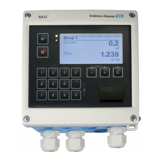
RA33
Batch Controller
These Instructions are Brief Operating Instructions; they are
not a substitute for the Operating Instructions pertaining to
the device.
For detailed information, refer to the Operating Instructions
and other documentation.
Available for all device versions via:
• Internet: www.endress.com/deviceviewer
• Smart phone/Tablet: Endress+Hauser Operations App
Solutions
Services
Advertisement
Table of Contents

Related Manuals for Endress+Hauser RA33


Summary of Contents for Endress+Hauser RA33
- Page 1 These Instructions are Brief Operating Instructions; they are not a substitute for the Operating Instructions pertaining to the device. For detailed information, refer to the Operating Instructions and other documentation. Available for all device versions via: • Internet: www.endress.com/deviceviewer • Smart phone/Tablet: Endress+Hauser Operations App...
- Page 2 RA33 Order code: XXXXX-XXXXXX Ser. no.: XXXXXXXXXXXX Ext. ord. cd.: XXX.XXXX.XX Serial number www.endress.com/deviceviewer Endress+Hauser Operations App A0023555 Endress+Hauser...
-
Page 3: Table Of Contents
RA33 Table of contents Table of contents About this document ............. . 3 Document conventions . - Page 4 About this document RA33 WARNING This symbol alerts you to a dangerous situation. Failure to avoid this situation can result in serious or fatal injury. CAUTION This symbol alerts you to a dangerous situation. Failure to avoid this situation can result in minor or medium injury.
- Page 5 RA33 About this document Symbol Meaning Symbol Meaning Reference to graphic … Series of steps Result of a step Visual inspection 1.1.4 Symbols in graphics Symbol Meaning Symbol Meaning 1, 2, 3,... Item numbers … Series of steps A, B, C, ...
-
Page 6: Basic Safety Instructions
Basic safety instructions RA33 Basic safety instructions Safe operation of the device is only guaranteed if the Operating Instructions have been read and the safety instructions they contain have been observed. Requirements for the personnel The personnel must fulfill the following requirements for its tasks: ‣... -
Page 7: It Security
RA33 Incoming acceptance and product identification IT security Our warranty is valid only if the device is installed and used as described in the Operating Instructions. The device is equipped with security mechanisms to protect it against any inadvertent changes to the settings. -
Page 8: Name And Address Of Manufacturer
• Approvals as per order version ‣ Compare the information on the nameplate with the order. Name and address of manufacturer Name of manufacturer: Endress+Hauser Wetzer GmbH + Co. KG Address of manufacturer: Obere Wank 1, D-87484 Nesselwang Model/type reference: RA33 Certificates and approvals 3.5.1... -
Page 9: Dimensions
RA33 Mounting Dimensions 144 (5.67) 77 (3.03) 138 (5.43) 103.1 (4.06) A0013438 1 Dimensions of the device in mm (in) 160 (6.3) 148 (5.83) A0014169 2 Dimensions of the mounting plate for wall, pipe and panel mounting in mm (in) -
Page 10: Mounting Requirements
Mounting RA33 138 (5.43) A0014171 3 Dimensions of the panel cutout in mm (in) 7.7 (0.3) 120 (4.72) A0014610 4 Dimensions of DIN rail adapter in mm (in) Mounting requirements With the appropriate accessories, the device with field housing is suitable for wall mounting, pipe mounting, panel mounting and DIN rail installation. -
Page 11: Mounting
RA33 Mounting NOTICE Overheating of the device due to insufficient cooling ‣ To avoid heat buildup, please always ensure that the device is sufficiently cooled. Operating the device in the upper temperature limit range decreases the operating life of the display. - Page 12 Mounting RA33 A0014283 6 Panel mounting Attach the seal (item 1) to the housing. A0014173 7 Preparing the mounting plate for panel mounting Screw the threaded rods (item 2) into the mounting plate (dimensions → 2, 9).
- Page 13 RA33 Mounting A0014284 8 Panel mounting Push the device into the panel cutout from the front and attach the mounting plate to the device from the rear using the 4 screws provided (item 3). Fasten the device in place by tightening the threaded rods.
- Page 14 Mounting RA33 A0014177 10 DIN rail mounting Attach the device to the DIN rail from the front and close the DIN rail clips. 4.4.4 Pipe mounting A0014178 11 Preparing for pipe mounting Pull the steel belts through the mounting plate (dimensions → 2, 9) and fasten them to the pipe.
-
Page 15: Post-Mounting Check
RA33 Mounting A0014179 12 Pipe mounting Attach the device to the mounting plate and fasten it in place using the 4 screws provided. Post-mounting check To install the Batch Controller and the associated temperature sensors, observe the general installation instructions according to EN 1434 Part 6. -
Page 16: Electrical Connection
Electrical connection RA33 Electrical connection Connection instructions WARNING Danger! Electric voltage! ‣ The entire connection of the device must take place while the device is de-energized. CAUTION Pay attention to additional information provided ‣ Before commissioning, ensure that the supply voltage corresponds to the specification on the nameplate. - Page 17 RA33 Electrical connection Signal ground for 0/4 to 20 mA input + 0/4 to 20 mA input Density (current input) Signal ground for 0/4 to 20 mA input + pulse input (voltage or contact) Flow (Optionally pulse or current - pulse input (voltage or contact)
- Page 18 Electrical connection RA33 5.2.1 Opening the housing A0014368 14 Opening the housing of the device Terminal assignment labeling Terminals Endress+Hauser...
-
Page 19: Connecting The Sensors
RA33 Electrical connection Connecting the sensors 5.3.1 Flow Flow sensors with external power supply A0013521 15 Connecting a flow sensor Voltage pulses or contact sensors including EN 1434 Type IB, IC, ID, IE Current pulses 0/4 to 20 mA signal... - Page 20 Electrical connection RA33 Settings for flow sensors with pulse output The input for voltage pulses and contact sensors is divided into different types according to EN1434 and provides a power supply for switching contacts. Pulse output of the flow Setting at the...
- Page 21 RA33 Electrical connection Pulse output of the flow Setting at the Electrical connection Comment sensor Rx33 Active current Pulse I The switching threshold is between 8 mA and 13 mA A0015363 A0015357 A Sensor Rx33 Namur sensor (as per Pulse ID/IE up to...
- Page 22 Electrical connection RA33 Temperature transmitter connection A0047822 A = without external power supply of the transmitter, B = with external power supply of the transmitter Terminals 90, 91: transmitter power supply Terminals 52, 53: temperature input To ensure the highest level of accuracy, we recommend using the RTD 4-wire connection, as this compensates for measurement inaccuracies caused by the mounting location of the sensors or the line length of the connecting cables.
-
Page 23: Outputs
RA33 Electrical connection Outputs 5.4.1 Analog output (active) This output can be used either as a 0/4 to 20 mA current output or as a voltage pulse output. The output is galvanically isolated. Terminal assignment, → 16. 5.4.2 Pulse output (active) Voltage level: •... - Page 24 Electrical connection RA33 A0014600 17 Connection of Ethernet TCP/IP, Modbus TCP Ethernet, RJ45 Cable entry for Ethernet cable 5.5.2 Modbus TCP (optional) The Modbus TCP interface is used to connect the device to higher-order systems to transmit all measured values and process values. The Modbus TCP interface is physically identical to the Ethernet interface →...
-
Page 25: Post-Connection Check
RA33 Electrical connection RxD/TxD (+) RxD/TxD (-) further instrumentation A0047099 18 Connection of Modbus RTU 5.5.4 Printer interface / RS232 (optional) The printer/RS232 interface is galvanically isolated (test voltage: 500 V) and is used to connect a printer. It is connected via a 3-pin plug-in terminal in the housing cover. -
Page 26: Operation Options
Operation options RA33 Operation options General information regarding operation The Batch Controller can be configured using operating keys or with the help of the "FieldCare" operating software. The operating software, including the interface cable, is available as an order option, i.e. it is not included in the basic scope of delivery. - Page 27 RA33 Operation options 6.2.1 Operating elements 3 operating keys, "-", "+", "E" Esc/Back function: Press "-" and "+" simultaneously. Enter/Confirm entry function: Press "E" 14 function keys Start / stop function: Press "Start" to start a batching process. Press "Stop" to pause the batch that is currently running.
- Page 28 Connect the device to the PC via USB. Create project in File/New menu. Select Communication DTM (CDI Communication USB). Add device EngyCal RA33. Click Connect. Start parameter configuration. Continue with device configuration in accordance with these Operating Instructions for the device.
-
Page 29: Operating Matrix
RA33 Operation options NOTICE Undefined switching of outputs and relays ‣ During configuration with FieldCare, the device may assume undefined statuses! This may result in the undefined switching of outputs and relays. Operating matrix A complete overview of the operating matrix, incl. all of the configurable parameters, can be found in the appendix of the Operating Instructions. -
Page 30: Commissioning
Commissioning RA33 Expert menu The Expert menu provides access to all of the operating positions of the device, including fine-turning and service functions. • Skip directly to the parameter via Direct Access (on device only) • Service code to display service parameters (via PC operating software only) •... - Page 32 *71557775* 71557775 www.addresses.endress.com...
Need help?
Do you have a question about the RA33 and is the answer not in the manual?
Questions and answers