
Related Manuals for Endress+Hauser RMS621


Summary of Contents for Endress+Hauser RMS621
- Page 1 Operating Instructions RMS621 Energy Manager BA182R/09/en/08.05 51009170 Software version:...
- Page 2 RMS621 Brief overview For quick and easy commissioning: Safety instructions Page 8 ⇓ Installation Page 11 ⇓ Wiring Page 13 ⇓ Display and operating elements Page 23 ⇓ Commissioning Page 28 Quick start via the navigator to device configuration for standard operation.
- Page 3 RMS621 Brief operating instructions " Caution! The information contained in these Operating Instructions serves as a guide to help you commission your device easily, i.e. the most important settings are listed here but special functions (e.g. tables, corrections etc.) are not.
- Page 4 RMS621 Display Group 1 Display mask: 3 values Value 1 (...4): Mass flow, Mass sum, Heat sum Group 2: select to above system e.g. flow 1, pressure 1, temperature 1.1, heat flow 1. Exit set-up Exit set-up by operating ESC...
- Page 5 RMS621 Group 2: select to above system e.g. temp. 1.1, temp. 1.2, mass flow 1, mass sum 1. Exit set-up Exit set-up by operating ESC a number of times and acknowledging with Display By operating any key you can enter the main menu and select the required group including all the relative display values: Display ->...
- Page 6 RMS621 Steam applications Input variables: flow, pressure, temperature1, (temperature2) Flow Pulse/PFM (e.g. Vortex) Analog (e.g. Vortex) Differential pressure (e.g. orifice) Flow input Flow input Special flow meters Flow sensor: operating volume Flow sensor: operating volume Differential pressure/orifice.../steam Terminal connection – Flow transmitter with active signal: e.g. select terminal A10 and connect flow meter to terminal A10(+)/11(-).
-
Page 7: Table Of Contents
RMS621 Table of contents Table of contents Safety instructions ....8 11.2 Flow measurement configuration ... . 67 Designated use . -
Page 8: Designated Use
Safety instructions RMS621 Safety instructions Safe operation of the Flow and Energy Manager is only guaranteed if these Operating Instructions have been read and the safety instructions have been observed. Designated use The Energy Manager is a unit for monitoring energy and flows in water and steam applications. It can be used in both heating and cooling systems. -
Page 9: Notes On Safety Conventions And Icons
RMS621 Safety instructions Notes on safety conventions and icons The safety instructions in these Operating Instructions are labelled with the following safety icons and symbols: " Caution! This symbol draws attention to activities or procedures that can lead to defective operation or to destruction of the device if not carried out properly. -
Page 10: Identification
Identification RMS621 Identification Device designation 2.1.1 Nameplate Compare the nameplate on the device with the following diagram: Fig. 3: Energy manager legend plate (example) Order code and unit series number Protection class and allowable ambient temperature Power supply Temperature sensor input with measurement range... -
Page 11: Installation
RMS621 Installation Installation Installation conditions The permitted ambient temperature (see "Technical data" Section) must be observed when installing and operating. The device must be protected against the effects of heat. 3.1.1 Dimensions Observe the device length of 135 mm (corresponds to 8TE). More dimensions can be found in Section 10 "Technical data". -
Page 12: Post-Installation Check
Installation RMS621 3.2.1 Installing extension cards You can equip the device with various extension cards. A maximum of three slots are available in the device for this. The slots for the extension cards are marked with B, C and D (→ Fig. 5) on the device. -
Page 13: Wiring
RMS621 Wiring Wiring Quick wiring guide Fig. 6: Slot assignment (basic unit) Terminal assignment Terminal (item no.) Terminal assignment Slot Input + 0/4 to 20 mA/PFM/pulse input 1 A top, front (A I) Current/PFM/pulse input 1 Ground for 0/4 to 20 mA/PFM/pulse input... -
Page 14: Connecting The Measuring Unit
Wiring RMS621 + 0/4 to 20 mA/pulse output 1 E bottom, rear (E IV) Current/pulse output 1 - 0/4 to 20 mA/pulse output 1 + 0/4 to 20 mA/pulse output 2 Current/pulse output 2 - 0/4 to 20 mA/pulse output 2... - Page 15 RMS621 Wiring 4.2.1 Power supply connection " Caution! • Before wiring the device, ensure that the supply voltage corresponds to the specification on the nameplate. • For the 90 to 250 V AC version (mains connection), a switch marked as a separator, as well as an overvoltage organ (rated current ≤...
- Page 16 Wiring RMS621 Passive sensors Connection method for sensors which are supplied with power by means of the sensor power supply integrated in the device. Fig. 9: Connecting a passive sensor, e.g. to input 1 (slot A I). Item 1: pulse signal...
- Page 17 RMS621 Wiring Flow sensor with open collector output Note! Select an appropriate dropping resistor R, so that = 20 mA is not exceeded. max. Flow sensor with passive current output (4 to 20 mA) Flow sensor with active current output (0/4 to 20 mA)
- Page 18 Wiring RMS621 Pressure sensor with passive current output (4 to 20 mA) 4.2.3 Connection of outputs The device has two galvanically isolated outputs which can be configured as an analog output or an active pulse output. In addition, an output for connecting a relay and transmitter power supply is available.
- Page 19 RMS621 Wiring 4.2.4 Extension card connection Fig. 13: Extension card with terminals Terminal assignment of Universal extension card Terminal (item no..) Terminal assignment Slot Input and output 24 V sensor power supply 1 B, C, D top, front (B I, C...
- Page 20 Wiring RMS621 Terminal (item no..) Terminal assignment Slot Input and output + RTD power supply 2 B, C, D top, rear (B II, C RTD input 2 II, D II) + RTD sensor 2 - RTD sensor 2 - RTD power supply 2...
- Page 21 RMS621 Wiring Installation/dimensions Mounting instructions: • The mounting location must be free from vibrations. • The permitted ambient temperature during operation is -20 to +60C (-4 to +140 °F). • Protect the device against the effects of heat. Procedure for panel mounting: Provide a panel cutout of 138+1.0 x 68+0.7 mm (5.43"+0.04"...
-
Page 22: Post-Connection Check
Wiring RMS621 Post-connection check After completing the device's electrical installation, carry out the following checks: Device status and specifications Notes Is the device or cable damaged (visual inspection)? Electrical connection Notes Does the supply voltage match the information on the nameplate? -
Page 23: Operation
RMS621 Operation Operation Display and operating elements Note! Depending on the application and version, the Flow and Energy Manager offers a wide range of configuration options and software functions. Help text is available for nearly every operating item to assist when programming the device. This help text can be called up by pressing the "?"... -
Page 24: Local Operation
Operation RMS621 5.1.1 Display Fig. 17: How the display of the energy computer appears Item: 1: measured value display Item: 2: display of configuration menu item – A: row of key icons – B: current configuration menu – C: configuration menu activated for selection (highlighted in black). - Page 25 RMS621 Operation Using the Palm keyboard Fig. 18: Example: editing an identifier with the Palm keyboard Using the cursor keys, place the cursor in front of the character before which another character should be entered. If the entire text should be deleted and rewritten, move the cursor completely to the right.
-
Page 26: Error Message Display
Operation RMS621 5.2.3 Operating example A detailed description of on-site operation with an application as an example can be found in Section 6.4 ’User-specific applications’. Error message display The device differentiates between two types of errors: • System error: this group comprises all the device errors, e.g. communication errors, hardware errors, etc. -
Page 27: Communication
RMS621 Operation Event buffer Main menu Diagnosis Event buffer In the event buffer, the last 100 events, i.e. fault messages, notices, limit values, power failure etc. are recorded in chronological order with the time of occurrence and counter reading. Error list The error list provides assistance in quickly localising current device errors. -
Page 28: Commissioning
Commissioning RMS621 Commissioning Function check Make sure that all post-connection checks have been carried out before you commission your device: • See Section 3.3 ’Post-installation check’ • Checklist Section 4.3 ’Post-connection check’ Switching on the measuring device 6.2.1 Basic unit Once the operating voltage is applied, the green LED (= device operating) lights up if no fault is present. -
Page 29: Device Configuration
RMS621 Commissioning Error messages After switching on or configuring the device, the message "Communication problem" appears briefly on the remote display/operating unit until a stable connection has been established. If this error message is displayed during operation, please check the wiring to the Energy Manager and ensure that the baudrate and the device address match the Energy Manager. - Page 30 Commissioning RMS621 Function (menu item) Description Group For selecting individual groups with display values. Display For displaying the groups alternately, setting in the setup menu"Display". Error list For quickly localising current device errors. Counter val For reading off and, if necessary, resetting all the totalizers.
- Page 31 RMS621 Commissioning 6.3.3 Main menu - Setup The Setup menu is used for configuring the Energy Manager. The following subsections and tables list and describe all the configuration parameters of the Energy Manager. Procedure when configuring the Energy Manager Select system units (device settings).
- Page 32 Commissioning RMS621 Function (menu item) Parameter setting Description Alarm response Fault category Default set-up - Alarm response when process errors occur. As per the factory Random setting, all process errors are signalled by a warning message. By selecting "Random", additional operating items appear in...
- Page 33 RMS621 Commissioning Setup → Inputs Note! Depending on the version, 4 to 10 current, PFM, pulse and RTD inputs are available in the energy computer to record the flow, temperature and pressure signals. Flow inputs The Energy Manager processes all common flow measurement methods (volume, mass, differential pressure).
- Page 34 Commissioning RMS621 Function (menu item) Parameter setting Description gal/bbl 31.5 (US), 42.0 (US), 55.0 Definition of technical unit Barrel (bbl), given in gallons per (US), 36.0 (Imp), 42.0 barrel. (Imp), User def. US: US gallons 31.0 Imp: Imperial gallons User def.: free to set the conversion factor.
- Page 35 RMS621 Commissioning Function (menu item) Parameter setting Description Expan. coeff. 0 to 9.9999e-XX Correction factor for compensating the temperature effect on the flow transmitter. This factor is often indicated on the nameplate for vortex flowmeters, for example. If no value is known for the expansion coefficient or if this has already been compensated by the device itself, please set 0 here.
- Page 36 Commissioning RMS621 Special flow meters Function (menu item) Parameter setting Description Special flow meters Differential pressure 1, 2, Configuration of individual or several differential pressure transmitters (DPT). Mean flow Note! Only use if your DP transmitter outputs a pressure-scaled signal (mbar, inH 0 etc.)
- Page 37 RMS621 Commissioning Function (menu item) Parameter setting Description Factor K-factor for describing the resistance coefficient of E+H Pitot tubes (see data sheet). Correction Possibilities for correcting the flow measurement by offset, signal damping, flow cut off, expansion coefficient of the device (e.g.
- Page 38 Commissioning RMS621 Function (menu item) Parameter setting Description Range 1 (2, 3) start 0.0000 to 999999 Start value for the differential pressure at 0 or 4 mA, defined for the pressure transmitter in range 1 (2, 3) Note! Only active after a terminal has been assigned.
- Page 39 RMS621 Commissioning Pressure inputs Function (menu item) Parameter setting Description Identifier Pressure 1-3 Name of pressure sensor, e.g. ’pressure in’ (max. 12 characters). Signal Select Selects the signal of the pressure sensor. If ’Default’ is set, the 4-20 mA device works with a fixed default pressure.
- Page 40 Commissioning RMS621 Temperature inputs Function (menu item) Parameter setting Description Identifier Temperature 1-6 Name of temperature sensor, e.g. ’Temp 1’ (max. 12 characters). Signal Select Selects the signal of the temperature sensor. If ’Default’ is set, 4-20 mA the device works with a fixed default temperature.
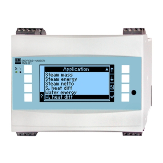
- Page 41 RMS621 Commissioning Setup → Applications Energy Manager applications: • Steam: Mass - heat quantity - net heat quantity - heat difference • Water: Heat quantity - heat difference Up to three different applications can be calculated simultaneously. The configuration of an application is possible without restricting the applications available up to now in the operating status.
- Page 42 Commissioning RMS621 Function (menu item) Parameter setting Description Flow direct. Constant Information on the direction of flow in the circuit with Changing bidirectional operation. Note! Only for the Bidirectional operating mode. Dir. signal Terminals Terminal for connecting the direction signal output of the flow transmitter.
- Page 43 RMS621 Commissioning Function (menu item) Parameter setting Description Time base .../s; .../min; .../h; .../d Time basis for the flow unit in the format: X per time unit selected. Heat flow kW, MW, kcal/time, Defines the heat quantity per the time unit set previously or Mcal/time, Gcal/time, the thermal performance.
- Page 44 Commissioning RMS621 Function (menu item) Parameter setting Description Heat 0 to 99999999.9 Heat totalizer of the application selected. Can be configured Heat (-) * and reset. Mass 0 to 99999999.9 Mass totalizer of the application selected. Can be configured Mass (-) * and reset.
- Page 45 RMS621 Commissioning If displaying one to three values in a group, all values with the name of the application and identifier (e.g. heat totalizer) and the related physical unit are displayed. As of four values, only the values and the physical unit are displayed.
- Page 46 Commissioning RMS621 Setup → Outputs Analog outputs Please note that these outputs can be used as both analog and pulse outputs; the desired signal type can be selected for each setting. Depending on the version (extension cards), 2 to 8 outputs are available.
- Page 47 RMS621 Commissioning Pulse outputs The pulse output function can be configured with active, passive output or relay. Depending on the version, 2 to 8 pulse outputs are available. Function (menu item) Parameter setting Description Identifier Pulse 1 to 8 An identifier can be assigned to the pulse output in question for a better overview (max.
- Page 48 Commissioning RMS621 Function (menu item) Parameter setting Description Pulse Type Negative Makes it possible to output pulses in a positive or negative Positive direction (e.g. for external electronic totalizers): • ACTIVE: the device-internal power supply is used (+24 V) • PASSIVE: external power supply necessary •...
- Page 49 RMS621 Commissioning Function (menu item) Parameter setting Description Simulation 0.0 Hz - 0.1 Hz - 1.0 Hz - The function of the pulse output is simulated with this setting. 5.0 Hz - 10 Hz - 50 Hz - Simulation is active if the setting is not "off". Simulation ends if 100 Hz - 200 Hz - 500 Hz you leave this item.
- Page 50 Commissioning RMS621 Function (menu item) Parameter setting Description Hysteresis -99999 to 99999 Specify set point switch-back threshold to suppress set point bounce. Time delay 0 to 99 s Time span of limit value violation before it is displayed. Suppresses peaks in the sensor signal.
-
Page 51: User-Specific Applications
RMS621 Commissioning Set-up → Service Service menu. Setup (all parameters) Service. Function (menu item) Parameter setting Description Preset Resets the device to the delivery status with the factory default settings (protected by service code). Note! This resets all the parameters you configured. - Page 52 Commissioning RMS621 1. Flow transmitter (Setup Inputs - Flow inputs) Flow 1 Signal: PFM K-factor: 8.9 Thermal exp. coeff: 4.88x10 (see example on left-hand side) 2. Pressure sensor (Setup/ Pressure): Pressure 1 Signal: 4 to 20 mA, Start value 0.005 bar,...
-
Page 53: Maintenance
RMS621 Maintenance Fig. 24: Automatic changing of different display groups Maintenance No special maintenance work is required for the device. Accessories Identifier Order code ® RS232 serial interface cable with 3.5 mm jack plug, with ReadWin 2000 PC software RMS621A-VK... -
Page 54: Trouble-Shooting
Trouble-shooting RMS621 Trouble-shooting Trouble-shooting instructions Always begin trouble-shooting using the following checklists if faults occur after commissioning or during operation. Different questions will guide you to the cause of the error and will suggest appropriate remedial action. System error messages... -
Page 55: Process Error Messages
RMS621 Trouble-shooting Process error messages Display Cause Remedy Config error: • Incorrect or incomplete programming or loss of • Check whether all necessary items have been calibration data defined with plausible values. • Pressure • Contradictory terminal assignment (→ Section 6.3.3 Main menu - Setup) •... - Page 56 Trouble-shooting RMS621 Display Cause Remedy Cable open circuit: "channel name" "signal name) Input current at current input smaller than 3.6 mA • Check sensor configuration. (with setting 4 to 20 mA) or larger than 21 mA. • Check function of the sensor.
-
Page 57: Spare Parts
RMS621 Trouble-shooting Display Cause Remedy • Minimum temp. difference Minimum temperature differential configured is Reduce low flow cut off if necessary. (see Section undershot, i.e. temperature differential valued at 6.3.3) zero. Spare parts Fig. 25: Energy Manager spare parts Item no.. - Page 58 Trouble-shooting RMS621 Item no.. Order number Spare part RMS621A-TA Temperature extension card (Pt100/Pt500/Pt1000) complete, incl. terminals and securing frames RMS621A-UA Universal extension card (PFM/pulse/analog/transmitter power supply unit) complete, incl. terminals and securing frames 51000780 Mains terminal 51004062 Relay terminal/transmitter power supply unit...
-
Page 59: Return
RMS621 Trouble-shooting Return For a return, e.g. in case of repair, the device must be sent in protective packaging. The original packaging offers the best protection. Repairs must only be carried out by your supplier's service organisation. An overview of the service network can be found on the address page of these Operating Instructions. -
Page 60: Technical Data
Technical data RMS621 Technical data 10.0.1 Input Measured variable Current, PFM, pulse, temperature Input signal Flow, differential pressure, pressure, temperature, density Measuring range Measured variable Input Current • 0/4 to 20 mA +10% overreach • Max. input current 150 mA •... - Page 61 RMS621 Technical data 10.0.2 Output Output signal Current, pulse, transmitter power supply (TPS) and switching output Galvanic isolation Basic unit: Connection with Powe Input 1/2 Input 1/2 Temperatu Output 1/2 Interface terminal 0/4 to 20 mA/ TPS unit re input 1/...
- Page 62 Technical data RMS621 Max. number: • 8 x 0/4 to 20 mA/pulse (depends on the number of extension cards) • 6 x digital passive (depends on the number of extension cards) Signal sources All available multifunctional inputs (current, PFM or pulse inputs) and results can be freely allocated to the outputs.
- Page 63 RMS621 Technical data Transmitter power supply and • Transmitter power supply unit, terminals 81/82 or 81/83 (optional universal extension cards external power supply 181/182 or 181/183): Max. output voltage 24 V DC ± 15% Impedance < 345 Ω Max. loop current 22 mA (at U >...
- Page 64 Technical data RMS621 Medium Variable Range Temperature measuring range 0 to 800 °C (32 to 1472 °F) Steam Pressure measuring range 0 to 1000 bar (0 to 14504 psi) Measurement and calculation interval 500 ms 10.0.5 Installation conditions Installation instructions...
- Page 65 RMS621 Technical data 10.0.7 Mechanical construction Design, dimensions Fig. 26: Housing for top-hat rail as per EN 50 022-35; dimensions in mm (dimensions in inches in brackets) Weight • Basic unit: 500 g (1.1 lb) (in maximum configuration with extension cards) •...
- Page 66 10.0.9 Certificates and approvals CE mark The measuring system meets the legal requirements of the EC Directives. Endress+Hauser confirms successful testing of the device by affixing to it the CE mark. Ex approval Information about currently available Ex versions (ATEX, FM, CSA, etc.) can be supplied by your E+H Sales Centre on request.
-
Page 67: Appendix
RMS621 Appendix Appendix 11.1 Definition of important system units Volume 1 barrel, definition see ’Setup → Application’ 1 US gallon, corresponds to 3.7854 litres igal Imperial gallon, corresponds to 4.5609 litres 1 litre = 1 dm 1 hectolitre = 100 litres corresponds to 1000 litres corresponds to 28.37 litres... - Page 68 Appendix RMS621 11.2.1 Flow calculation based on the differential pressure method RMx621 has 2 ways of measuring differential pressure: • Traditional differential pressure method • Improved differential pressure method Traditional differential pressure method Improved differential pressure method Only accurate in design parameter (pressure, temperature,...
- Page 69 RMS621 Appendix The flow is calculated as follows: ƒ = correction factor (K-factor or value from the correction table) d = internal diameter ∆P = differential pressure ρ = density in operating status Example: Flow measurement in a steam line with a Deltatop Pitot tube •...
- Page 70 Appendix RMS621 How should the Energy Manager and the sensor be configured? Sensor type Unit 1. Traditional No data available on the pipe diameter and diameter ratio ß (k-factor for Pitot tube). method a) (Default) Flow input (operating volume or mass) Square root curve e.g.
- Page 71 RMS621 Appendix Fig. 28: Splitting Range mode Mean value computation Mean value computation gives you the opportunity of measuring an input variable using several sensors at different points and then getting the mean value from them. This function helps if several measuring points are required in a system in order to determine the measured variable with sufficient accuracy.
- Page 72 RMS621 Index Index Active sensors ....... . . 15 Nameplate ........10 Alarm response .
- Page 73 Set-up table Customer Expansion cards Order code Type Slot Unit no. Universal Operator Temperature Application Measurement Application type Flow Signal type Start value End value Pulse value Eng. Units Pressure Signal type Start value End value Eng. Units Temperature Signal type Start value End value Eng.
- Page 75 Overview function matrix Alarm response Text input General info Basic set-up Date-Time System eng. Code Display Group Scrolling display Display Contrast units Fault Category Text input Unit ID User Group 1.to.6 Swit. time OIML main unit Date System eng. units Alarm lim.
- Page 77 www.endress.com/worldwide BA182R/09/en/08.05 51009170 FM+SGML6.0 ProMoDo...
Need help?
Do you have a question about the RMS621 and is the answer not in the manual?
Questions and answers