Endress+Hauser RA33 Brief Operating Instructions
Batch controller
Hide thumbs
Also See for RA33:
- Operating instructions manual (32 pages) ,
- Operating instructions manual (82 pages) ,
- Instructions (3 pages)

Related Manuals for Endress+Hauser RA33


Summary of Contents for Endress+Hauser RA33
- Page 1 Brief Operating Instructions RA33 Batch Controller KA00299K/09/en/13.10 71119860 SW-Version: 1.00.xx...
-
Page 2: Table Of Contents
Table of contents RA33 Table of contents 1 Safety instructions ..........3 1.1 Designated use . -
Page 3: Safety Instructions
RA33 Safety instructions Safety instructions Safe operation of the device is only guaranteed if the Operating Instructions have been read and the safety instructions they contain have been observed. Designated use The batch controller is a batching and dosing manager for the batching of any media or mineral oils. -
Page 4: Notes On Safety Conventions And Icons
Safety instructions RA33 Notes on safety conventions and icons The safety instructions in these Operating Instructions are labeled with the following safety icons and symbols: " Caution! This symbol draws attention to activities or procedures that can lead to defective operation or to destruction of the device if not carried out properly. -
Page 5: Identification
RA33 Identification Identification Device tag 2.1.1 Nameplate Compare the nameplate on the device with the following diagram: a0014625 Fig. 1: Nameplate of the batch controller (example) Device tag Order code and serial number Supply voltage Power consumption Firmware version Approvals, if available... -
Page 6: Scope Of Delivery
Installation RA33 Scope of delivery The scope of delivery of the batch controller comprises: • Batch controller (field housing) • Brief Operating Instructions in paper form, Operating Instructions and additional documentation (on CD-ROM) • Optional interface cable and DVD set with FieldCare Device Setup parameter configuration software •... -
Page 7: Dimensions
RA33 Installation • The permitted storage temperature range is -40 to +85°C (-40 to +185 °F); storage in the temperature limit ranges is possible for a limited time only (maximum of 48 hours). Dimensions a0013438 Fig. 2: Dimensions of the device... - Page 8 Installation RA33 a0014169 Fig. 3: Mounting plate for wall, pipe and panel mounting a0014171 Fig. 4: Panel cutout Endress+Hauser...
-
Page 9: Installation
RA33 Installation a0014610 Fig. 5: Dimensions of the top-hat rail adapter Installation The device with field housing and accessories is suitable for wall mount, pipe mounting, panel mounting and top-hat rail installation. The orientation is only determined by the legibility of the display. Connections and outputs are fed out of the bottom of the device. - Page 10 Installation RA33 a0014170 Fig. 6: Wall mounting 3.4.2 Panel mounting Make the panel cutout in the required size, dimensions → å 4. Attach the seal (item 1) to the housing. a0014283 Fig. 7: Panel mounting Endress+Hauser...
- Page 11 RA33 Installation Screw the threaded rods (item 2) into the mounting plate (dimensions → å 3). a0014173 Fig. 8: Preparing the mounting plate for panel mounting Push the device into the panel cutout from the front and attach the mounting plate to the device from the rear using the 4 screws provided (item 3).
- Page 12 Installation RA33 3.4.3 Support rail/top-hat rail (to EN 50 022) Fasten the top-hat rail adapter (item 1, dimensions → å 5) to the device using the screws provided (item 2) and open the top-hat rail clips. a0014176 Fig. 10: Preparing for top-hat rail mounting Attach the device to the top-hat rail from the front and close the top-hat rail clips.
- Page 13 RA33 Installation 3.4.4 Pipe mounting Pull the steel belts through the mounting plate (dimensions → å 3) and fasten them to the pipe. a0014178 Fig. 12: Preparing for pipe mounting Attach the device to the mounting plate and fasten it in place using the 4 screws provided.
-
Page 14: Post-Installation Check
Wiring RA33 Post-installation check Note! For installing the batch controller and the associated temperature sensors, observe the general installation instructions according to EN 1434 Part 6. Wiring Connection requirements Warning! Note that the entire electrical connection must be carried out only while the device is de-energized. - Page 15 RA33 Wiring Terminal assignment Terminals Terminal assignment Inputs + RTD power supply Temperature (Optionally RTD or current input) - RTD power supply + RTD sensor - RTD sensor + 0/4 to 20 mA input Ground for 0/4 to 20 mA input...
- Page 16 Wiring RA33 Power supply L for AC + for DC N for AC - for DC 4.2.1 Open housing a0014368 Fig. 15: Opening the housing of the batch controller Terminal assignment labeling Terminals Endress+Hauser...
-
Page 17: Connecting The Sensors
RA33 Wiring Connecting the sensors 4.3.1 Flow Flow sensors with external power supply a0013521 Fig. 16: Connecting a flow sensor Voltage pulses or contact sensors including EN 1434 Type IB, IC, ID, IE Current pulses 0/4 to 20 mA signal (not in combination with MID approval option) - Page 18 Wiring RA33 4.3.2 Temperature Connecting the RTD sensors a0014185 1 = 4-wire connection, 2 = 3-wire connection, 3 = 2-wire connection Terminals 1, 2, 5, 6: T warm Terminals 3, 4, 7, 8: T cold Temperature transmitter connection a0014186 1 = without external power supply of the transmitter, 2 = with external power supply of...
-
Page 19: Outputs
RA33 Wiring Outputs 4.4.1 Analog output This output can be used either as a 0/4 to 20 mA current output or as a voltage pulse output. The output is galvanically isolated. For the terminal assignment, refer to → ä 14. - Page 20 Wiring RA33 a0014600 Fig. 18: Ethernet TCP/IP, Modbus TCP connection Ethernet, RJ45 Cable entry for Ethernet cable 4.5.2 Modbus TCP (optional) The Modbus TCP interface is used to connect the device to higher-order systems to transmit all measured values and process values. The Modbus TCP interface is physically identical to the Ethernet interface (→...
-
Page 21: Post-Connection Check
RA33 Wiring 4.5.4 Printer interface / RS232 (optional) The printer/RS232 interface is galvanically isolated (testing voltage: 500 V) and is used to connect a printer. It is connected via a 3-pin plug-in terminal in the housing cover. a0014602 Fig. 20: Printer connection via RS232... -
Page 22: Operation
Operation RA33 Operation General notes for operation The batch controller can be configured using keys or using the "FieldCare" operating software. The operating software, including the interface cable, is available as an order option, i.e. it is not part of the basic scope of delivery. - Page 23 RA33 Operation Slow flashing of the red LED (approx. 0.5 Hz): the device has been put into bootloader mode. Fast flashing of the red LED (approx. 2 Hz): in normal operation: maintenance required. During firmware update: data transmission active. Red LED illuminated constantly: device error.
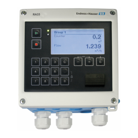
- Page 24 Operation RA33 5.2.3 Display a0014551 Fig. 22: Display of the batch controller (example) Display group 1: no batch active. Flow, temperature, preset counter Display group 2: batch active. Flow, volume counter, preset counter Note! A list of the icons is provided in the Appendix in the operating instructions.
-
Page 25: Operating Matrix
RA33 Operation Operating matrix For a complete overview of the operating matrix including all configurable parameters, see ’Appendix’ section in the operating instructions on CD-ROM. Language Drop-down list with all available operating languages. Select the language of the device. Display/operation menu •... -
Page 26: Commissioning
Commissioning RA33 Expert menu The Expert menu offers access to all operating options of the device, including fine tuning and service functions. • Jump directly to parameters via Direct Access (only on the device) • Service code for displaying service parameters (via PC operating software only) •... -
Page 27: Quick Commissioning/Make It Run
RA33 Commissioning Quick commissioning/make it run For quick commissioning of the "standard" batch controller application, you only have to enter a few operating parameters in the menu Setup. Prerequisites for quick commissioning: • RTD temperature sensor, 4-wire direct connection Menu/setup É... - Page 28 www.endress.com/worldwide KA00299K/09/en/13.10 71119860 FM+SGML6.0 ProMoDo...
Need help?
Do you have a question about the RA33 and is the answer not in the manual?
Questions and answers