
Related Manuals for Siemens POL8T2.40/STD


Summary of Contents for Siemens POL8T2.40/STD
- Page 1 POL8T2.40/STD Climatix Capacitive Touch Panel Basic Documentation Smart Infrastructure A6V11348824_en--_a 2018-04-10...
-
Page 2: Table Of Contents
Configuring the Climatix touch panel .............22 Set screen brightness ................22 Set the time and date ................. 22 Test the serial ports ................... 23 Set the language ..................23 Maintenance and care .................24 2 | 30 Siemens A6V11348824_en--_a Smart Infrastructure 2018-04-10... - Page 3 Technical specifications............... 25 Technical data ...................25 Interface description ..................27 LED indicators ...................28 DIP switches ....................29 Dimensions (in mm) ...................29 3 | 30 Siemens A6V11348824_en--_a Smart Infrastructure 2018-04-10...
-
Page 5: About This Document
This symbol marks texts that contain safety information to prevent wrong operation. This symbol marks passages you should read with special care. Texts marked with this symbol provide additional information, notes and so on. 5 | 30 A6V11348824_en--_a Siemens Smart Infrastructure 2018-04-10... -
Page 6: Trademarks
This document may be duplicated and distributed only with the expressed permission of Siemens, and may be provided only to authorized persons or companies with the requisite technical knowledge. Siemens reserves the right to make any modification to this document without prior notice. 1.4.4 Quality assurance These documents were prepared with great care. -
Page 7: Document Use / Request To The Reader
Siemens assumes no liability to the extent allowed under the law for any losses resulting from a failure to comply with the aforementioned points or for the improper compliance of the same. -
Page 8: Overview
Time scheduler and trend view functions via HMI-TOOLS ● Data tag management via HMI-TOOLS ● Time sync with Climatix controller via HMI-TOOLS ● Graphical extendable database with HVAC pictures and animations via HMI-TOOLS ● Support C-like script language programming 8 | 30 Siemens A6V11348824_en--_a Smart Infrastructure 2018-04-10... -
Page 9: Topology
The application in the Climatix controller must support Modbus communication via RS485 interface and/or local service interface (T-HI). With Climatix POL6XX controller Climatix POL6XX communication concept (here C600) With Climatix POL4XX controller Climatix POL4XX communication concept (here POL42X) 9 | 30 A6V11348824_en--_a Siemens Smart Infrastructure 2018-04-10... -
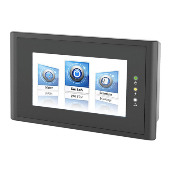
Page 10: Product Design
The following is the mechanical design of the Climatix capacitive touch panel, POL8T2.40. Description Description Display / touch screen RS485 communication port LED indicators DIP switches Label Recesses for a mounting clip USB-A port Power supply connection USB-B port 10 | 30 Siemens A6V11348824_en--_a Smart Infrastructure 2018-04-10... -
Page 11: Delivery Scope
Overview Delivery scope 2.4 Delivery scope Name Figure Quantity Touch panel Power supply terminal Mounting clips 11 | 30 A6V11348824_en--_a Siemens Smart Infrastructure 2018-04-10... -
Page 12: Safety Instructions
Make sure that both ends of the cable are connected tightly and firmly. The RS485 port is a communication port. It cannot be used for programming. 12 | 30 Siemens A6V11348824_en--_a Smart Infrastructure 2018-04-10... -
Page 13: Mounting And Connecting
Check the package content for visible signs of transport damage and for completeness. Note: Do not install parts damaged during shipment. Contact your Siemens representative in the event of damaged parts. Check operating Note the information in the following sections of these operating instructions before... -
Page 14: Mount The Climatix Touch Panel
Grounding Terminal- Field wiring terminal for connection of equipment-grounding conductor shall be green-colored or plainly identified on or adjacent to connector or provided on instruction manual and shipped with the device by “G”, “GR”, “GRD”, 14 | 30 Siemens A6V11348824_en--_a Smart Infrastructure 2018-04-10... -
Page 15: Connect Power Supply
This provides a pathway for electrostatic discharge and blocks high-frequency interference. (Recommendation: Resistance, 1 M Ω; Capacitance, 4700 pF.) 4. Switch off the power supply. 5. Insert the remaining wire ends into the mains terminal, and secure them with a screwdriver. 15 | 30 A6V11348824_en--_a Siemens Smart Infrastructure 2018-04-10... -
Page 16: Connect Configuration Pc
USB Type B male connector on one end. 1. Connect the USB cable to the USB-A port on the Climatix touch panel. 2. Connect the other end of the USB cable to the configuration PC. 16 | 30 Siemens A6V11348824_en--_a Smart Infrastructure 2018-04-10... -
Page 17: Connect Climatix Controller
2. Connect an RS485 connector on a communication cable to the Climatix touch panel. 3. Connect the other RS485 connector on the communication cable to the controller. For safety instructions, see Notes on communication [➙ 12]. 17 | 30 A6V11348824_en--_a Siemens Smart Infrastructure 2018-04-10... -
Page 18: Switch On The Climatix Touch Panel
Check the connected cables and change them as needed. Climatix touch panel has a DEMO application in order to show main functionalities and features. Please download your own application developed with HMI-TOOL configuration software. 18 | 30 Siemens A6V11348824_en--_a Smart Infrastructure 2018-04-10... -
Page 19: Operating The Climatix Touch Panel
You can configure the customized keyboard for an operating element in the configuration software. ASCII keyboard Numeric keypad 19 | 30 A6V11348824_en--_a Siemens Smart Infrastructure 2018-04-10... -
Page 20: System Keyboard
*.zip Preparation To create an upgrade image on a USB stick: 1. Contact Siemens regional company to get an upgrade file (.zip) for your touch panel firmware. 2. Format the USB stick as FAT32 format. 3. Extract the zip file (MLO, ubi.img, u-boot.img and uImage) to USB stick root. -
Page 21: Upgrade Gui Application
5. Wait until a request for confirmation of GUI download appears. 6. Confirm the GUI download process. 7. After the upgrade process is completed, the Climatix touch panel restarts automatically. 8. The Climatix touch panel runs new GUI application. 21 | 30 A6V11348824_en--_a Siemens Smart Infrastructure 2018-04-10... -
Page 22: Configuring The Climatix Touch Panel
6.1 Set screen brightness Press Brightness, and adjust the screen brightness. 6.2 Set the time and date Press Date / time and use + or - to set the date and time, and press Ok. 22 | 30 Siemens A6V11348824_en--_a Smart Infrastructure 2018-04-10... -
Page 23: Test The Serial Ports
7. In the monitor software, enter test data and send it. 8. If the Receiving a character textbox displays the same data, the test is successful. 6.4 Set the language Press Language, select the desired display language and press Ok. 23 | 30 A6V11348824_en--_a Siemens Smart Infrastructure 2018-04-10... -
Page 24: Maintenance And Care
Do not clean the Climatix touch panel with compressed air or steam jet blowers. Do not use aggressive solvents or scouring powder. 24 | 30 Siemens A6V11348824_en--_a Smart Infrastructure 2018-04-10... -
Page 25: Technical Specifications
60529 ● Front IP 65 ● Rear panel IP 20 ESD protection EN 61000-4-2 Housing material ABS + PC Configuration software HMI-TOOLS (third party engineering software) Touchpad 2-point high-precision capacitive touch screen 25 | 30 A6V11348824_en--_a Siemens Smart Infrastructure 2018-04-10... - Page 26 Dimensions (mm) 150 × 93 × 38.5 Cut-out (mm) 141 × 84 Weight (kg) 0.28 Ordering data Article type (ASN) POL8T2.40/STD Material (SSN) S55626-H824-A100 Minimum order quantity Product package* Touch panel Mounting clips Power supply terminal Power supply and communication cables are not included in product package.
-
Page 27: Interface Description
DC 5 V out, max. 500 mA Data - Data + Ground Serial port interface Figure RS485 Connect to controller port REF (for RS485) Data - RS485 B- (for RS485 connection) Data + RS485 A+ (for RS485 connection) 27 | 30 A6V11348824_en--_a Siemens Smart Infrastructure 2018-04-10... -
Page 28: Led Indicators
The three LED indicators are located on the front of the Climatix touch panel. Marking Indicator name Color Mode Description Power supply Green Powered on No power Operation Yellow No detected fault CPU fault detected in the device Communication Yellow Flashing Communication in progress communication 28 | 30 Siemens A6V11348824_en--_a Smart Infrastructure 2018-04-10... -
Page 29: Dip Switches
(1 – 5) Function 00000 Normal operation mode 01000 Setting mode 10000 Calibrate the touch screen 10100 Enter Android system 00100 Firmware upgrade mode DIP switch status: ON=1, OFF=0 8.5 Dimensions (in mm) POL8T2.40/STD 29 | 30 A6V11348824_en--_a Siemens Smart Infrastructure 2018-04-10... - Page 30 © Beijing Siemens Cerberus Electronics Ltd., 2018 Issued by Beijing Siemens Cerberus Electronics Ltd. Technical specifications and availability subject to change without notice. Smart Infrastructure No.1, Fengzhi East Road, Xibeiwang Haidian District, 100094 BEIJING, China +86 10 64768806 www.siemens.com/buildingtechnologies Document ID: A6V11348824_en--_a...
Need help?
Do you have a question about the POL8T2.40/STD and is the answer not in the manual?
Questions and answers