Table of Contents
Advertisement
Quick Links
POWER SUPPLY FOR SINGLE AND
MULTI-RESIDENTIAL VIDEO DOOR ENTRY SYSTEMS
WITH "SOUND SYSTEM" CALL
INSTALLATION AND OPERATION MANUAL
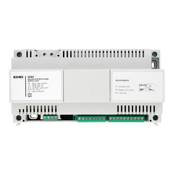
Art. 6680
Product is according to CE mark and directives:
- EC Directives 89/336/EEC and following norms.
- EC Directives 73/23/EEC and following norms.
power supplies constitute SELV sources in compliance with the requirements stipulated in Article 411.1.2.2 of CEI standard 64-8
(ed. 1998).
Production is subject to costant surveillance:
D V E
Cod. S6I.668.00E
ed. 02
4/2004
Advertisement
Table of Contents

Subscribe to Our Youtube Channel
Related Manuals for Elvox 6680


Summary of Contents for Elvox 6680
- Page 1 POWER SUPPLY FOR SINGLE AND MULTI-RESIDENTIAL VIDEO DOOR ENTRY SYSTEMS WITH “SOUND SYSTEM” CALL INSTALLATION AND OPERATION MANUAL Art. 6680 Product is according to CE mark and directives: - EC Directives 89/336/EEC and following norms. - EC Directives 73/23/EEC and following norms.
- Page 2 - Before cleaning or maintenance, disconnect the set. Power supply Art. 6680 must be placed in a dry place far - In the event of a fault and/or poor operation of the device, from sources of dust and heat.
- Page 3 Technical specifications of power supply type 6680 - (6680/V03) Type 6680 is the basic power supply for all video door entry systems with SOUND SYSTEM call and is equipped with an elec- tronic double tone generator, which replaces conventional alternative calling with a buzzer or bell. The sound is emitted with two different tones (present on terminals C1-C2) thereby allowing the user to immediately identify the source of the call (main entrance, gate, garage, etc.).
- Page 4 TERMINALS FOR MONITOR TYPE 6300, 6301, 6303, 6500, TERMINALS FOR MONITOR TYPE 6000, 6003 6501 V1: Input for connection of 75 Ohm video cable in systems Interphone receiver with coax cable; input for connection of video signal V1 in systems without coax cable. Interphone microphone Common audio line V2: Output for connection of 75 Ohm video cable or 75 Ohm...
- Page 5 POWER SUPPLY TERMINALS SUGGESTED CONDUCTOR COLOUR (Ref. Cable type 61/001) Interphone receiver SKY BLUE Interphone microphone WHITE CONNECTIONS TO Common interphone line PINK MONITORS + Negative terminal of monitor supply voltage BLACK SECT. 1mm INTERPHONES Positive terminal of 18V D.C. 0.8A monitor supply RED SECT.
- Page 6 "SOUND SYSTEM" SINGLE AND MULTIPLE RESIDENCE VIDEO DOOR ENTRY SYSTEM WITH POWER SUPPLY TYPE 6680 AND WITHOUT CONVERSATION PRIVACY MONITOR CABLE RISER B/W MONITOR 5 3 2 1 V type 6000 + Connect 75 Ohm resistor (sup- type 6200 +...
- Page 7 "SOUND SYSTEM" SINGLE AND MULTIPLE RESIDENCE VIDEO DOOR ENTRY SYSTEM WITH POWER SUPPLY TYPE 6680 WITHOUT CONVERSATION PRIVACY AND VIDEO DISTRIBUTOR ART. 5556/004 OR 6554 MONITOR CABLE RISER 5 3 2 1 V Connect 75 Ohm resistor (sup- 75ohm plied) to the last monitor, between B/W MONITOR terminals V2-M.
-
Page 8: Table Of Contents
"SOUND SYSTEM" SINGLE AND MULTIPLE RESIDENCE VIDEO DOOR ENTRY SYSTEM WITH POWER SUPPLY TYPE 6680 AND CONVERSATION PRIVACY MONITOR CABLE RISER 6 5 3 B/W MONITOR Connect 75 Ohm resistor (sup- type 6000 + plied) to the last monitor, between... - Page 9 The calls from entrance panel (C1) and from the apartment door but- ton (C2) are generated by the power supply Art. 6680, while the intercommunication call signal (C3) is supplied by the switching module Art.
-
Page 10: Cable
INTERCOMMUNICATING VIDEO DOOR ENTRY SYSTEM FOR SINGLE RESIDENCE WITH POWER SUPPLY 6680 AND SWITCHING MODULE TYPE 935A B/W MONITOR A- Video entrance panel Connect 75 Ohm resistor (sup- type 6000 + GALILEO SECURITY, GALILEO, 8100 plied) to the last monitor,... - Page 11 EXAMPLES OF WIRING DIAGRAMS FOR INTERCOMMUNICATING MONITORS AND INTERPHONES FOR SINGLE RESI- DENCE VIDEO DOOR ENTRY SYSTEM WITH SWITCHING MODULE TYPE 935A Fig. 1 Fig. 2 Two monitors and seven intercommunicating interphones. Three monitors and five intercommunicating interphones. B/W MONITOR B/W MONITOR type 6000 + type 6000 +...
-
Page 12: Type 6500
VARIATION 1 Wiring diagram with simultaneous activation of two or more monitors by power supply type 6582 Monitor cable riser The power supply type 6680 can simultaneously power two monitors type 6000, 6003, 6300, 6301, Max 2 monitor 6303 or one monitor type... -
Page 13: Power Supply
6600 - +U +I - +U C +I A B C Call repeater Power supply Call repeater type 934 Power supply type 6583 type 934 To power supply type 6583 type 6680 Mains Mains To power supply Mains type 6680... - Page 14 18V D.C. 2A with intermittent operation. Mains 1st MONITOR 2nd MONITOR Power supply CABLE RISER CABLE RISER type 6680 If a line with excessive voltage drops powers a single monitor, you can use the power supply type 6582. Mains 15 O Power supply type 6583 N.B.
- Page 15 Mains Mains Monitor type 6301 type 6501 Interphone type 6200 Additional bell Additional bell type 860A type 860A Power supply type 6680 Mains Mains Monitor Monitor type 6300 type 6300 type 6303 type 6303 type 6500 type 6500 Additional bell...
- Page 16 6200 RELAY RELAY type 170/101 type 170/101 Maximum load Maximum load Power supply 3A - 230V 3A - 230V type 6680 Monitor type 6300 Monitor C 1 2 15 type 6303 type 6301 Mechanical Mechanical type 6500 type 6501...
- Page 17 If type 6150 is installed inside interphone type 6200, the landing call cannot be used. Monitor type 6000 type 6003 Mains Interphone type 6200 Power supply type 6680 M1 V1 V2 M2 AU C2 1 2 3 - 6 7 8 - +T AM 15 O S1 Mains Power supply type 6680...
- Page 18 STANDARD VIDEO DOOR ENTRY SYSTEM WIRING DIAGRAM VARIATIONS WITH COAX CABLE VARIATION 8 Wiring diagram for switching on the stair light or other services powered by AC mains by means of relay type 170/001. To switch on the stair light in this case, press push-button number To activate the auxiliary service press the push-button with 1.
-
Page 19: S1 6 7 8 - +Tam 15 0 S11
The capacity of the contacts of the monitor push-button is 24 V D.C./A.C. 0.5A max. Monitor type 6000 type 6003 Mains Power supply type 6680 M1 V1 V2 M2 AU C2 1 2 3 - 6 7 8 - +T AM 15 O S1 Interphone... - Page 20 The electronic ding-dong ringtone card type 6150 can be installed in interphone type 6200 to convert the sound generated by the power supply type 6680. N.B . The loudspeaker must be disconnected from the interphone's motherboard and connected to connector "A-A" on the interphone.
- Page 21 8875 type 8872 CHCHCH S 6 5 3 2 1 V 6 5 3 2 To power supply To power supply type 6680 type 6680 Monitor type 6000 type 6003 Interphone type 6200 can also be connected without monitor.
- Page 22 To power supply INSTALLING THE MODULE ON PETRARCA SERIES type 6680 INTERPHONES 6200 - 6201 - Open the interphone Fig. 1 - Snap off the plastic lamina by exerting pressure on it (Fig. 1B) - Insert the card in its seat and fix it with the screw supplied (Fig.
- Page 23 6501 type 6600 S/S1 S/S1 The red LEDs are powe- red by the power supply 6680 and must not exceed a total of 20 in number. For larger numbers, use an additional power supply. - + C S - + N.O.
- Page 24 6 7 8 - +T AM 15 0 S1 16X24V 3W with type 832/030 VARIATION 17 Connection of camera Art. 559A with power supply Art. 6680. A- Entrance panel series GALILEO B- Additional push-button for lock C- Electric lock 12V~ D- Camera with speech unit Art.
- Page 25 For night filming, light the viewing area of the secondary camera with an additional bulb, using relay type 170/001. This bulb can be either infrared for B/W filming, or white light type for colour filming. For the other connections, follow the standard diagrams for power supply type 6680.
- Page 26 +D +D at any time. CH CH Mains AU AU AU AU Power supply type 6680 6E 6E M1 M1 V1 V1 V2 V2 M2 M2 AU AU C2 C2 - +T +T AM 15 15...
- Page 27 Remember to leave in place the 75 Ohm load resistance to the input terminals "IN". Connect the resistances supplied with the V2-M terminals of the last monitor. For the other connections, refer to the wiring diagrams for the power supply type 6680. VARIATION 21 Wiring diagram for transformer type M832-...
- Page 28 6600 Monitor terminals Monitor terminals Monitor terminals series Petrarca series 6300-6500 series 6600 To power supply type 6680 - +U +I Power supply Distributor type 6582 type 5556/004 Mains N.B. In power supply type 6582 short circuit terminals A-B-D.
- Page 29 The wiring diagram only illustrates the monitor cable riser connection to a video floor distributor in a video door entry system. To make the remaining connections, follow the standard wiring diagrams for power supply type 6680, except for the monitor cable riser connection (without video floor distributor) which must be replaced by the one shown in this diagram.
- Page 30 The wiring diagram only illustrates the monitor cable riser connection to a video floor distributor in a video door entry system. To make the remaining connections, follow the standard wiring diagrams for power supply type 6680, except for the monitor cable riser connection (without video floor distributor) which must be replaced by the one shown in this diagram.
- Page 31 FAULT DETECTION AND CONTROLS ® Monitor switched OFF: Check voltage across terminals - and + (15-20 V dc). Check that the power supply generates the elec- tronic call notes; connect a loudspeaker of 50÷100 Ohm between terminals - and CH (6E and 8) of the monitor and make a call from the entrance panel.
- Page 32 15 (15V ac). Each monitor has its own AC bell, and in this way it differs from previous models. In this operating mode the power supply Art. 6680 completely substitutes Art. 6580.
- Page 33 "B". MONITOR Art. 6600 MAINS CABLE POWER SUPPLY Art.61/001 Art. 6680 Art.61/003 S 6 5 3 2 1 V M1 V1 V2 M2 1 2 3 - 6 7 8 - +T AM 15 0 S1 CABLE Art.61/001...
- Page 34 5 5 4 4 3 3 2 2 1 1 - +U Relay To power supply Art. 170/001 Power supply Art. 6680 Art. 6583 Mains N.B. Set the shunt present on the terminal block side into "BC" position. Monitor cable riser...
- Page 35 INTERPHONE Art. 8870 Art. 8871 6 5 3 2 INTERPHONE Art. 620R TO POWER SUPPLY ART. 6680 CHCHCH S 6 5 3 2 1 V TO POWER SUPPLY ART. 6680 INTERPHONE CH S 6 CH S 6 3 2 1 V...
- Page 36 With type 6150, the door call and intercommunicating call cannot be connected. The following versions used with power supply type 6680 in Sound System version may also be used with power supply type 6680 in version with A.C. call for monitors type 6300, 6303, 6500, 6000+6200+6150, 6003+6200+6150: see versions: 1, 3, 5, 6, 8, 9, 11, 19, 20, 21, 22, 23.
Need help?
Do you have a question about the 6680 and is the answer not in the manual?
Questions and answers