Table of Contents
Advertisement
Quick Links
Advertisement
Table of Contents

Related Manuals for CRU QX118


Summary of Contents for CRU QX118
- Page 1 QX118 Receiving Frame User Manual...
- Page 2 CDSG. Use of the full QX118 product is subject to all of the terms and conditions of this User Manual and the above referenced License.
-
Page 3: Table Of Contents
QX118 Receiving Frame User Manual Table of Contents 1. General Information ........................ 4 1.1. Introduction ........................4 1.2. Package Contents ......................4 1.3. Safety Information ......................4 1.4. Identifying Parts ......................5 1.5. LED Behavior ....................... 5 2. Setup ............................. 7 2.1. -
Page 4: General Information
SHIPS module it holds. This User Manual will show you how to install and properly set up the QX118 receiving frame, how to in- stall and remove SHIPS modules, and provide other operational information you will need to get the most out of your product. -
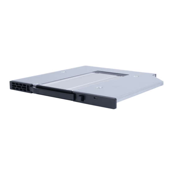
Page 5: Identifying Parts
The module inside the slot is being accessed by your Flickering computer, but the module is at risk of data throttling due to high temperatures. The fan inside of the QX118 has failed. Contact Technical Solid Support for a replacement. - Page 6 QX118 Receiving Frame User Manual LED Name Color State Description The module inside the slot is being accessed by your Flickering computer, but the inside the QX118 has failed. Contact Technical Support for a replacement.
-
Page 7: Setup
Turn off your computer. Disconnect the power cord, and remove the computer cover. Slide the QX118 receiving frame into a vacant 9mm or 9.5mm optical drive bay. If necessary, secure the QX118 to the drive bay with M2 screws of your own. - Page 8 If necessary, install a host bus adapter card (HBA) with at least one (1) OCuLink port into your com- puter. Refer to the HBA's user manual for installation instructions. Connect an OCuLink SFF-8611 cable (sold separately) to your HBA. Connect the other end of the OCuLink cable to the OCuLink port on the rear of the QX118.
-
Page 9: Disable Windows Fast Startup
2.2. DISABLE WINDOWS FAST STARTUP “Fast startup” must be disabled in Windows 10 and Windows 8.1 to ensure that data from the QX118 is read properly. Here are the instructions for how to do so with Windows 10. - Page 10 QX118 Receiving Frame User Manual Under Related Power Settings in the right column, select Additional power settings. On the left column of the new window, select Choose what the power buttons do.
- Page 11 QX118 Receiving Frame User Manual Select Change settings that are currently unavailable. Uncheck Turn on fast startup (recommended).
- Page 12 QX118 Receiving Frame User Manual Click the Save changes button.
-
Page 13: Operation
Power off your computer. If you have hot swapping capability, then you may ignore this step. Unlock the module slot door. If you have the Push-Button Version: Push the button located on the right side of the QX118 to re- lease the module slot door. Then move the door out of the way. -
Page 14: Safe Ships Module Removal
If hot swapping is not available, then failure to turn off your computer before removing or installing a SHIPS module may result in data loss. CRU has designed the QX118 to support hot swapping. However, your entire system must support hot swapping, including your motherboard, BIOS/UEFI, CPU, operating system, and host bus adapter. - Page 15 Unlock the module slot door. If you have the Push-Button Version: Push the button located on the right side of the QX118 to re- lease the module slot door. Then move the door out of the way.
-
Page 16: Product Support
QX118 Receiving Frame User Manual 4. PRODUCT SUPPORT Your investment in CRU products is backed up by our free technical support for the lifetime of the prod- uct. Contact us through our website, cru-inc.com/support or call us at 1-800-260-9800 or... -
Page 17: Appendix A. Table Of Specifications
PCIe Gen3 compliant per the Add in Card criteria of the PCIe Specification 3.1. Each CRU SHIPS Module ships with an M.2 NVMe SSD preinstalled. Documentation for the SHIPS module is provided in the SHIPS Documentation, available by request. OCuLink SFF-8612 connectors require an OCuLink SFF-8611 cable to mate... - Page 18 This page is intentionally left blank.
- Page 19 This page is intentionally left blank.
- Page 20 This page is intentionally left blank.
Need help?
Do you have a question about the QX118 and is the answer not in the manual?
Questions and answers