Table of Contents

Related Manuals for Enotec COMTEC 6000 DustEx


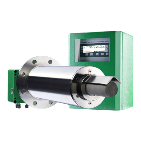
Summary of Contents for Enotec COMTEC 6000 DustEx
- Page 1 Installation and Operation Manual COMTEC 6000 ATEX – DustEx ® / CO Analyzer System OXITEC 5000 ATEX – DustEx ® Analyzer System Version 05 OXITEC Software Version: 4.13 COMTEC Software Version: 4.13 Doc.-ID: COM_OXI_Dust_11022020...
- Page 2 ENOTEC. This results in a considerably increased service life compared to „glued or cemented“ competitors measuring cells, which have a tendency to leak or crack during operation. ENOTEC's sensors have a proven gas gas-tight design, providing greater measuring accuracy, durability and longer working life time.
-
Page 3: Table Of Contents
Display Board ............32 4.2.10 Pre-purge time 4.2.11 Automatic Calibration (ACAL) Warranty 4.2.12 ENOTEC REMOTE 4.2.13 Measuring units Declaration of Conformity 4.2.14 Language Index 4.2.15... -
Page 5: System Description
CO sensors. There are no constructive differences between both systems. Info References to the CO sensor are only applicable to the COMTEC 6000 DustEx analyzer system. System Overview Figure 1 - System overview Safe Area Electronic unit SME5 / IP66 Max. -
Page 6: Measuring Principle
(e.g. at night or during the weekend). Frequently cooling down and heating up of the probe results in thermal stress of the hot probe parts (heater, thermocouple and sensor) and reduces their product life. ENOTEC will not accept any responsibility for resultant damage. -
Page 7: Storage Instructions
Storage instructions ENOTEC equipment and spares are to be stored in a dry and ventilated environment at temperatures between -40 °C to +80 °C (-40 °F to 176 °F). Paint fumes, silicone sprays, etc. must be avoided in the storage environment. -
Page 8: Name Plates
The system order code contains detailed system information which is detailed in the system test report and supplied with the system. Nameplate of the SME-53 electronic unit COMTEC 6000 DustEx OXITEC 5000 DustEx Nameplate of the SME-54 electronic unit... -
Page 9: Installation
Installation Installation and Operation Manual - DustEx Installation Warning The system is not equipped with an external power-off switch. The line voltage switch/fuse/breaker must be installed and be in accordance with local technical standards and should be near to the electronic unit and must be clearly marked as such. -
Page 10: Installation Requirements For Probe Cable
Installation ® ® Installation and Operation Manual - COMTEC / OXITEC DustEx Installation Requirements for Probe Cable Warning The shield of the probe cable must only be connected at the electronic housing at the PE terminal. Under no circumstance should the shield also be connected at the probe. Abide by the maximum cable length (Max. -
Page 11: Access To The Terminals
Installation Installation and Operation Manual - DustEx Access to the Terminals Warning Before removing the terminal covers, switch off the mains voltage to the system. Switch the mains voltage on only after attaching the terminal cover. After the installation has been completed, live parts may no longer be accessible. -
Page 13: Wiring Diagram Of The Electronic Unit
(12..24V DC - Ext. supply) brown brown/white Thermocouple (O sensor) Calibration release (12..24V DC – Ext. supply) green white Analogue outputs (active 4-20mA) COe sensor (COMTEC 6000 DustEx only) white/red 2 sensor white/red 1 red 4 red 3 sensor Doc.-ID: COM_OXI_Dust_11022020... -
Page 14: Electrical Wiring Diagram - Oxitec Dustex
Installation ® ® Installation and Operation Manual - COMTEC / OXITEC DustEx Electrical Wiring Diagram - OXITEC DustEx Figure 8 - Wiring diagram of OXITEC 5000 DustEx O analyzer Doc.-ID: COM_OXI_Dust_11022020... -
Page 15: Electrical Wiring Diagram - Comtec Dustex
Installation Installation and Operation Manual - DustEx Electrical Wiring Diagram - COMTEC DustEx Figure 9 - Wiring diagram of COMTEC 6000 DustEx O / CO analyzer Doc.-ID: COM_OXI_Dust_11022020... -
Page 16: Installation Of The Probe
For probe lengths exceeding 2000 mm, a support must be mounted inside the duct (every 2m) to prevent the probe and mounting tube from flexing or bending. ENOTEC recommends installing the probe horizontally for the fastest possible response time. A vertical (90 °) installation decreases the response time significant. -
Page 17: Mounting Of The Counter Flange At The Duct
Installation Installation and Operation Manual - DustEx Mounting of the Counter Flange at the Duct The counter flange ADP-6007-S01 (with tube) must be welded gastight to the duct wall (3) or alternatively the ADP- 6007 (without tube) must be welded gastight (3a) to the existing tube. The insulation (6) must be done by the customer. -
Page 18: Mounting Of The Probe
(or heated if necessary), to prevent its temperature from dropping below the acid dew point. Never leave the probe unheated in the running process for a longer period of time! Electrical heaters are available from ENOTEC. The bolts of the probe flange must always remain accessible. -
Page 19: Requirements For Pneumatic Cable Fep-0002
Installation Installation and Operation Manual - DustEx 2.13 Requirements for Pneumatic Cable FEP-0002 Note the minimum bending radius. FEP-0002R = 138 mm +50 °C +90 °C Max. Max. -5 °C -40 °C Min. Min. Temp. during operation Temp. during installation Doc.-ID: COM_OXI_Dust_11022020... -
Page 20: Preparation Of The Pneumatic Cable
Installation ® ® Installation and Operation Manual - COMTEC / OXITEC DustEx 2.14 Preparation of the pneumatic cable Tubing of the pneumatic cable FEP-0002 Clamp ring Support sleeve Both, the pneumatic tubing for the reference air (blue) and the test gas (green) have to be prepared with support sleeves , clamp rings and nuts... -
Page 21: Pneumatic Connections Of The Electronic Units
Installation Installation and Operation Manual - DustEx 2.16 Pneumatic Connections of the Electronic Units Tube Pump Version Instrument Air Version 1/4“ Testgas in Testgas in 1/4“ Testgas out Testgas out 1/4“ Reference air input Instrument air in 1/4“ Reference air output Reference air out 1/4“... -
Page 22: Initial Operation
Switch on the line voltage to the system. After a short power up information, the user is prompted to Select language, set the System date, System time, enter a TAG number and ENOTEC REMOTE code (only if option ENOTEC REMOTE is factory activated) and enter the probe cable length (COMTEC only). -
Page 23: Display - Probe Heating Phase
Initial Operation Installation and Operation Manual - DustEx Display - Probe Heating Phase The probe heating phase begins with the heating up of the O sensor. After this is concluded, the COe sensor begins its heating up phase. TAG number Rising probe temperature (or) waiting period (or) heater error... -
Page 24: Status Leds
Initial Operation ® ® Installation and Operation Manual - COMTEC / OXITEC DustEx Status LEDs Softkey Symbols Moves the selection one position upwards Alarm, - orange - is lit when an alarm has been activated (e.g. Moves the selection one position down- limit alarm) wards Leave an area... -
Page 25: Menu Overview And Explanations
Menu Overview and Explanations Installation and Operation Manual - DustEx Menu Overview and Explanations Menu Overview - SYS-MENU SYS-MENU System Information Actual measured values measured value (% O ) {may be ppm} -mA output 17A/B (mA) sensor input (mV) COe measured value (ppm or mg/m COe mA output (mA) COe sensor input (mV) Flow rate reference air (l/h) - Page 26 Menu Overview and Explanations ® ® Installation and Operation Manual - COMTEC / OXITEC DustEx Calibration results (cont.) ~~ Test gas data ~~ Test air (20,95 % O Test air (0 ppm CO) Test gas (e.g. 2,1 % O Test gas (e.g. 1000 ppm CO) ~~ Sensor raw data~~ voltage at test air (mV) voltage at test gas (mV)
- Page 27 Menu Overview and Explanations Installation and Operation Manual - DustEx Limit alarms Limit alarm 1 (O )(OFF/ON) ♦ at } visible when set to "ON" ♦ hysteresis Limit alarm 2 (COe)(OFF/ON) ♦ at } visible when set to "ON" ♦ hysteresis sensor calibration values cal.value - offset (mV) cal.value - slope (mV/dec)
- Page 28 System clock/TAG number System date (jjjj-mm-tt) System time (hh:mm:ss) ENOTEC REMOTE settings (optional) } Visible when ENOTEC REMOTE interface is activated ENOTEC REMOTE (ON/OFF) Passkey (8 digit code) } Visible when ENOTEC REMOTE is ON Range (Short / Medium / Maximum) Measuring units Temperature (°C / °F)
-
Page 29: Menu Explanations - Sys-Menu
Menu Overview and Explanations Installation and Operation Manual - DustEx Menu Explanations - SYS-MENU 4.2.1 Measuring Ranges (Scaling) The O Measuring range is linearly scaled and converted to a linear current output (0/ 4-20 mA). The parameter „O Measuring range from“ is the start value of the O range, leading to an output of 4,00 mA. -
Page 30: Coe Measuring Ranges (Scaling)
Menu Overview and Explanations ® ® Installation and Operation Manual - COMTEC / OXITEC DustEx 4.2.6 COe Measuring Ranges (Scaling) The COe Measuring range is linearly scaled and converted to a linear current output (0/ 4-20 mA). The parameter „COe Measuring range from“ is the start value of the COe range, leading to an output of 4,00 mA. -
Page 31: Automatic Calibration (Acal)
Menu Overview and Explanations Installation and Operation Manual - DustEx 4.2.11 Automatic Calibration (ACAL) Automatic calibration enables a cyclic, time-based or remote controlled calibration (using the digital input) of the sensors. The ACAL can be globally switched on or off and can only be started from the main screen of the display. When a 2 Point ACAL is set, a test gas bottle must be permanently connected and turned on. -
Page 32: Enotec Remote
The device configuration can also not be altered. Range limits the transmission power of the ENOTEC REMOTE module. Maximum = 100m, medium = 10m, short = 1m. The actual possible range may vary due to structural factors and the reception strength of the Smartphone/Tablet. -
Page 33: Load Factory Settings
Menu Overview and Explanations Installation and Operation Manual - DustEx 4.2.16 Load factory settings Loading factory settings will restore all original settings and values to the default values programmed in the factory. If activated, all set parameters and also values such as sensor calibration values and calibration results are lost. Take note of the sensor calibration values beforehand and re-enter them after the loading the factory settings. -
Page 34: System Checks
Menu Overview and Explanations ® ® Installation and Operation Manual - COMTEC / OXITEC DustEx System Checks + COe Sensor checks Source: Test air sensor .. mV = .. % COe sensor .. mV = .. ppm Flow rate .. l/h Source: Test gas sensor ... -
Page 35: Cal Menu
Menu Overview and Explanations Installation and Operation Manual - DustEx CAL MENU CAL MENU 1 point calibration, O 2 point calibration, O 1 point calibration, COe (COMTEC only) 2 point calibration, COe (COMTEC only) 1 point calibration, O + COe (COMTEC only) 2 point calibration, O + COe... -
Page 36: 1-Point Calibration
Menu Overview and Explanations ® ® Installation and Operation Manual - COMTEC / OXITEC DustEx 4.4.2 1-point calibration (O and/or COe) (manual) During the 1-point calibration of the sensor, the calibration offset is determined. Test air is hereby applied to the sensor. -
Page 37: Service And Maintenance
Service and Maintenance Installation and Operation Manual - DustEx Service and Maintenance Warning Before opening the electronic unit or the connection box the system must be voltage free. Minimum waiting time 5 s. The surrounding area have to be voltage free ,when working on the powered up system ... -
Page 38: Flow Rates For Test Air And Reference Air
Service and Maintenance ® ® Installation and Operation Manual - COMTEC / OXITEC DustEx Flow Rates for Test Air and Reference Air The systems are factory-set to the correct amounts of test air and/or reference air. The instrument air versions are designed for an inlet pressure of 1-10 bars. -
Page 39: Position Of The Adjustment Valves
Service and Maintenance Installation and Operation Manual - DustEx Position of the adjustment valves Figure 31 - Terminal cover of the SME-53 Electronic Unit showing the position of the reference air and test air valves below Adjusting Flow Rate (SME-54) With systems in 19“... -
Page 40: Replacing The Filter Head
Service and Maintenance ® ® Installation and Operation Manual - COMTEC / OXITEC DustEx Replacing the Filter Head Warning hot surface The probe may only be removed with heat-insulated gloves. Before removing the probe, always switch off the supply voltage to the electronic system. After removal, store the probe in a safe, protected place and wait until it has cooled down below 35°C/95°F. -
Page 41: Exchange Of Probe Inner Parts
Service and Maintenance Installation and Operation Manual - DustEx Exchange of Probe Inner Parts Switch off the electronic unit, take the probe out of the protection tube and wait until it has cooled down. Warning hot surface The probe may only be removed with heat-insulated gloves. Before removing the probe, always switch off the supply voltage to the electronic system. -
Page 42: Replacing The O
Service and Maintenance ® ® Installation and Operation Manual - COMTEC / OXITEC DustEx Replacing the O Sensor Note An exchange of the measuring cell is only necessary if the cell is leaking (erratic or incorrect measured values) Switch off the electronic unit, take the probe out of the protection tube and wait until it has cooled down. Warning hot surface The probe may only be removed with heat-insulated gloves. -
Page 43: Replacing The Coe Sensor (Comtec)
Service and Maintenance Installation and Operation Manual - DustEx 5.10 Replacing the COe Sensor (COMTEC) Caution Failure to observe this information may destroy the new replacement CO sensor. Sensor (via the software) SYS-MENU System Configuration Set CO Disable the CO measurement OFF Switch off the power supply of the analyzer system. -
Page 44: Seal The Coe Sensor Guide Tube
Service and Maintenance ® ® Installation and Operation Manual - COMTEC / OXITEC DustEx Prepare the new CO sensor as follows: Take the clamping ring, the O-ring, retainer ring and the cap nut and cover them over the COe sensor. Note: Mind the position of the bevel. -
Page 45: Relay Outputs / Functions And Correlations
Service and Maintenance Installation and Operation Manual - DustEx 5.11 Relay Outputs / Functions and Correlations The relay contacts are designed for 24V and 1A ~, 1A = (Exception: probe valve) Relay Contact Function Terminal System error* Normally closed Signals operation-critical errors X5 (19A/B) Maintenance Normally open... -
Page 46: Digital Inputs
Service and Maintenance ® ® Installation and Operation Manual - COMTEC / OXITEC DustEx 5.12 Digital Inputs The digital inputs are designed for a direct voltage of 12 V - 24 V DC for logical “High”. Logical “Low” corresponds to a voltage less than 1 V. -
Page 47: Status Messages
Status Messages Installation and Operation Manual - DustEx Status Messages Error Messages Error Relay signal Description Message contact output System 2.00 mA, The error can occur at any time and signalizes a failure of one of the Hardware error, when not set electronic components. - Page 48 If the error occurs again, switch the system on and off. If the error n error otherwise persists after restarting the system, contact an ENOTEC service point. The error can occur at any time and signals a short circuit either by COe sensor COe sensor 20.80mA...
-
Page 49: Alarm Messages
As long as the system is connected to AC power, the alarm has no impact. Only after restarting system will the time / date be incorrect. A possible timed automatic calibration can no longer work correctly. Unlisted alarm messages: Other messages cannot be remedied by the customer. Please contact an ENOTEC service point Service Messages Maintenance Relay... -
Page 50: Heater Control Unit
Status Messages ® ® Installation and Operation Manual - COMTEC / OXITEC DustEx Heater Control Unit The heater control unit (HCU-0001) is fail-safe (redundantly) constructed. It switches the probe heater off automatically when exceeding the operating temperature of the probe. The switch-off temperature is set at 810°C / 1490°F. -
Page 51: Troubleshooting
Troubleshooting Installation and Operation Manual - DustEx Troubleshooting Unsteady, widely varying measuring value (O Possible reasons Procedure Intermittent contact caused by wire breakage Eliminate bad/loose contact Intermittent contact inside the probe - internal mV connection Broken filter element Visual inspection by dismounting the probe Wrongly installed V-shield Probe has been installed without filter head display remains at the end of the measuring range or is higher than expected... - Page 52 Troubleshooting ® ® Installation and Operation Manual - COMTEC / OXITEC DustEx Local Displays correct, Output not correct Possible reasons Procedure Electronic unit is defective Check measuring range. Check whether the current value is outside the measuring range Electronic unit is defective Measure the mA output on the strip terminal.
-
Page 53: Technical Data
® ® Technical Data Installation and Operation Manual - COMTEC / OXITEC DustEx Technical Data Electronic Unit Housing: sheet steel powder coated; RAL6029 (GRP version optional) (SME-57, 19” rack optional) Safe Area Housing: IP66 IP Code: GFK cabinet: IP66 19“ housing: IP20 Display: LC Dot Matrix 240 x 64 - LED backlit... -
Page 54: Probe
Technical Data ® ® Installation and Operation Manual - COMTEC / OXITEC DustEx Probe Process gas temperature: up to 600 °C (1112 °F) Insertion depth: KES-6001: 470 mm KES-6002: 930 mm Measuring principle: Zirconium oxide for O MXP for Co Flue gas pressure: -50 mbar to +50 mbar (-0.725 PSIG to +0.725 PSIG) to atmosphere pressure... -
Page 55: Requirements For The Gas Supply
® ® Technical Data Installation and Operation Manual - COMTEC / OXITEC DustEx Requirements for the Gas Supply The analyzer system uses the connected instrument air continuously for the supply of reference air, and during calibration and system test respectively, for the supply of test air (test gas 1). Instrument air supply for reference air / test air Specification: According to ISO 8573-1 class 2... -
Page 56: Dimension Drawings
Dimension Drawings ® ® Installation and Operation Manual - COMTEC / OXITEC DustEx Dimension Drawings Dimensions of the Electronic Units Figure 43 - Field housing (sheet steel) IP65 Figure 44 - Electronic unit in 19 inch rack 4HE (aluminium) IP20 Figure 45 –... -
Page 57: Probe Dimensions
® ® Dimension Drawings Installation and Operation Manual - COMTEC / OXITEC DustEx Probe Dimensions Figure 46 - Dimensions of the probes KES6001 and KES6002 Doc.-ID: COM_OXI_Dust_11022020... -
Page 58: Counter Flange Dimensions
Dimension Drawings ® ® Installation and Operation Manual - COMTEC / OXITEC DustEx Counter Flange Dimensions Figure 47 - Dimensions of counter flange ADP-6007 for KES600X Figure 48 - Dimensions of counter flange ADP-6007-S01 for KES600X Doc.-ID: COM_OXI_Dust_11022020... -
Page 59: Probe Components
® ® Dimension Drawings Installation and Operation Manual - COMTEC / OXITEC DustEx Probe Components Figure 49 - KES600X80000 Probe Components Artikel number Description ASK-0003 Connection box MSR-600X-ST Probe tube FLD-1000 Probe flange gasket SIK-600X-2TH Probe inner part ZO2-60(0/1)1 Measuring cell MZD-0005 Metal-O-ring seal 0-R-002311... -
Page 60: Gas Plan
Dimension Drawings ® ® Installation and Operation Manual - COMTEC / OXITEC DustEx Gas plan Pneumatic version for Instrument air Pneumatic version with pumps SME-50000010 SME-50000020 Figure 50 - Gas plans Pressure control valve Filter Choke non return valve Choke non return valve Solenoid valve 3/2 ways Reference air pump / Test air pump Solenoid valve 3/2 ways... -
Page 61: Spare Parts
® ® Spare Parts Installation and Operation Manual - COMTEC / OXITEC DustEx Spare Parts Mounting Plates of the electronic Unit Parts List Test gas and reference air unit with internal pumps TRA-0017 Transformer prim. 2*115V, sec. 115V PLU-0028 Test air pump for SME5 720 l/h Test gas solenoid valve P01 for PGM-0001 SME53 - with pneumatic unit and... -
Page 62: Display Board
Spare Parts ® ® Installation and Operation Manual - COMTEC / OXITEC DustEx Figure 53 - Mounting plate 2 with HCU and COe sensor board (COMTEC only) Mounting plate 2 Parts List HCU-0001 Failsafe heater control 0-L-000180 Power board 0-A-000155 Mounting plate Terminal block X10 0-L-000107... -
Page 63: Warranty
E N O T E C W A R R A N T Y ENOTEC warrants that systems manufactured and sold by it will, upon shipment, be free of defects in workmanship or material. Should any failure to conform to this warranty become apparent during the relevant warranty periods, ENOTEC shall, upon prompt written notice from the purchaser, correct such nonconformity by repair or replacement of the defective part or parts. -
Page 64: Declaration Of Conformity
EC-directives as follows. Any unauthorized changes to the products, renders this declaration invalid. The manufacturer carries the sole responsibility for issuing this declaration. Manufacturer: ENOTEC GmbH Höher Birken 6 51709 Marienheide - Germany Tel.: +49 2264 45 78-0... - Page 65 / OXITEC DustEx EG- / EU-Konformitätserklärung - Sonden EC- / EU-Declaration of Conformity - probes Wir / We ENOTEC GmbH Höher Birken 6 D-51709 Marienheide Tel. 02264-4578-0 Fax 02264-4578-30 erklären hiermit, dass die Geräte: declare that the devices: und CO...
-
Page 66: Index
Index Menu Explanations A Time per test gas apply ..........2 Menu Overview ..............5 Access to the Terminals ............. 9 Mounting of the Probe ............6 Adjusting the Flow Rate............8 Adjusting the V-shield ............5 N C Name Plate ................ 6 Counter Flange ..............
Need help?
Do you have a question about the COMTEC 6000 DustEx and is the answer not in the manual?
Questions and answers