
Related Manuals for Enotec COMTEC 6000 ATEX GasEx


Summary of Contents for Enotec COMTEC 6000 ATEX GasEx
- Page 1 Installation and Operation Manual Explosion-Proof O /COe Analyzer System ® COMTEC 6000 ATEX GasEx Version: 19 for Software Version: 4.13 Doc.-ID: COMGAS_11022020_EN...
- Page 2 ENOTEC. This leads to a considerably increased service life compared to "glued or cemented" sensors that have a tendency to leak or crack during operation. All ENOTEC instruments are thoroughly tested in the factory and are subject to a strict ISO 9001 and internal quality assurance ®...
-
Page 3: Table Of Contents
Declaration of EC conformity - Electronics 91 4.2.10 Pre-purge time ..........49 4.2.11 Automatic Calibration (ACAL) ......49 Index 4.2.12 ENOTEC REMOTE ........... 50 4.2.13 Measuring units ..........50 4.2.14 Language ............50 4.2.15 Change system code ........ -
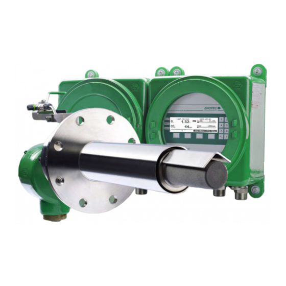
Page 4: System Description
System Description ® Installation and Operation Manual - COMTEC 6000 ATEX GasEx System Description System Overview Figure 1 - System Overview with explosion proof housing and probe Hazardous Area- Electronic unit / IP66 Max. ambient temp.:-20°C to +55°C (-4°F to + 131°F) Hazardous Area In-situ measuring probe / IP66 Max. - Page 5 ® System Description Installation and Operation Manual - COMTEC 6000 ATEX GasEx Figure 2 - System Overview with Safe Area housing Safe Area Electronic unit / IP66 Max. ambient temp.: -20°C to +55°C (-4°F to + 131°F) Hazardous Area In-situ measuring probe / IP66 Max.
-
Page 6: Measuring Principles
(heater, thermocouple and sensor) and reduces their product life. ENOTEC will not accept any responsibility for resultant damage. Storage instructions ENOTEC equipment and spares are to be stored in a dry and ventilated environment. Paint fumes, silicone sprays, etc. must be avoided in the storage environment. Doc.-ID: COMGAS_11022020_EN... -
Page 7: Name Plates
® System Description Installation and Operation Manual - COMTEC 6000 ATEX GasEx Name Plates The name plate of the probe contains year of manufacture, probe serial number, O sensor number and system order code. The system order code contains system information which details the system test report and is supplied with the system SME-5D SME-53... - Page 8 System Description ® Installation and Operation Manual - COMTEC 6000 ATEX GasEx Doc.-ID: COMGAS_11022020_EN...
- Page 9 ® System Description Installation and Operation Manual - COMTEC 6000 ATEX GasEx Doc.-ID: COMGAS_11022020_EN...
- Page 10 System Description ® Installation and Operation Manual - COMTEC 6000 ATEX GasEx Doc.-ID: COMGAS_11022020_EN...
- Page 11 ® System Description Installation and Operation Manual - COMTEC 6000 ATEX GasEx Doc.-ID: COMGAS_11022020_EN...
- Page 12 System Description ® Installation and Operation Manual - COMTEC 6000 ATEX GasEx Doc.-ID: COMGAS_11022020_EN...
- Page 13 ® System Description Installation and Operation Manual - COMTEC 6000 ATEX GasEx Doc.-ID: COMGAS_11022020_EN...
-
Page 14: Atex Certification - Electronics
System Description ® Installation and Operation Manual - COMTEC 6000 ATEX GasEx ATEX Certification - Electronics Doc.-ID: COMGAS_11022020_EN... - Page 15 ® System Description Installation and Operation Manual - COMTEC 6000 ATEX GasEx Doc.-ID: COMGAS_11022020_EN...
- Page 16 System Description ® Installation and Operation Manual - COMTEC 6000 ATEX GasEx Doc.-ID: COMGAS_11022020_EN...
- Page 17 ® System Description Installation and Operation Manual - COMTEC 6000 ATEX GasEx Doc.-ID: COMGAS_11022020_EN...
- Page 18 System Description ® Installation and Operation Manual - COMTEC 6000 ATEX GasEx Doc.-ID: COMGAS_11022020_EN...
- Page 19 ® System Description Installation and Operation Manual - COMTEC 6000 ATEX GasEx Doc.-ID: COMGAS_11022020_EN...
- Page 20 System Description ® Installation and Operation Manual - COMTEC 6000 ATEX GasEx Doc.-ID: COMGAS_11022020_EN...
- Page 21 ® System Description Installation and Operation Manual - COMTEC 6000 ATEX GasEx Doc.-ID: COMGAS_11022020_EN...
- Page 22 System Description ® Installation and Operation Manual - COMTEC 6000 ATEX GasEx Doc.-ID: COMGAS_11022020_EN...
- Page 23 ® System Description Installation and Operation Manual - COMTEC 6000 ATEX GasEx Doc.-ID: COMGAS_11022020_EN...
- Page 24 System Description ® Installation and Operation Manual - COMTEC 6000 ATEX GasEx Doc.-ID: COMGAS_11022020_EN...
- Page 25 ® System Description Installation and Operation Manual - COMTEC 6000 ATEX GasEx Doc.-ID: COMGAS_11022020_EN...
- Page 26 System Description ® Installation and Operation Manual - COMTEC 6000 ATEX GasEx Doc.-ID: COMGAS_11022020_EN...
- Page 27 ® System Description Installation and Operation Manual - COMTEC 6000 ATEX GasEx Doc.-ID: COMGAS_11022020_EN...
- Page 28 System Description ® Installation and Operation Manual - COMTEC 6000 ATEX GasEx Doc.-ID: COMGAS_11022020_EN...
- Page 29 ® System Description Installation and Operation Manual - COMTEC 6000 ATEX GasEx Doc.-ID: COMGAS_11022020_EN...
- Page 30 System Description ® Installation and Operation Manual - COMTEC 6000 ATEX GasEx Doc.-ID: COMGAS_11022020_EN...
-
Page 31: Installation
® Installation Installation and Operation Manual - COMTEC 6000 ATEX GasEx Installation Warning The device must be provided with an external power-off switch. The line voltage switch/fuse/breaker must be in accordance with the local technical standards and should be near to the electronic unit and must be clearly marked as such. -
Page 32: Installation Of Probe Signal Cable Fep-0007/8
Installation ® Installation and Operation Manual - COMTEC 6000 ATEX GasEx Installation of probe signal cable FEP-0007/8 Warning The shielding of the probe cable (FEP-0007 or FEP-008 (armoured)) must be connected only to the electronic unit ground (PE) clamp. In no case should the shield of the probe cable be also connected at the probe end. Max. -
Page 33: Access To The Terminals
® Installation Installation and Operation Manual - COMTEC 6000 ATEX GasEx Access to the terminals Warning Before removing the terminal covers, switch off the mains voltage to the system. Switch the mains voltage on only after attaching the terminal cover. After the installation has been completed, live parts may no longer be accessible. Figure 6 - Access to the Terminals Doc.-ID: COMGAS_11022020_EN... -
Page 34: Wiring Diagrams Of Comtec 6000 Gasex (Sme-5D And Ex Probe)
Installation ® Installation and Operation Manual - COMTEC 6000 ATEX GasEx Wiring diagrams of COMTEC 6000 GasEx (SME-5D and EX probe) Figure 7 - Wiring diagram of the COMTEC 6000 GasEx electronic unit Doc.-ID: COMGAS_11022020_EN... -
Page 35: Ferrite Sleeves
® Installation Installation and Operation Manual - COMTEC 6000 ATEX GasEx Ferrite Sleeves In order to avoid cable related disturbances to the electronic unit, the supplied ferrite sleeves are to be fitted as follows. CE-conformity is invalid, if these ferrite sleeves are not fitted! Ferrite Sleeves Cable Wires... -
Page 36: Installation Of The Probe
Installation ® Installation and Operation Manual - COMTEC 6000 ATEX GasEx Installation of the probe The flue gas temperature, pressure and all other process conditions must be in accordance with the specification. Leave enough space for insertion/removal of the probe and protection tube (if supplied) and ensure access to the measuring probe and/or connecting box. -
Page 37: Adjustment Of The Probe Filter Head V-Shield
® Installation Installation and Operation Manual - COMTEC 6000 ATEX GasEx Adjustment of the Probe Filter Head V-Shield Info Ascertain the flow direction of the process gas at the place of installation. Unscrew the retaining ring (clockwise) with a hook wrench ... -
Page 38: Insulation With Cooling Protection Tube
Installation ® Installation and Operation Manual - COMTEC 6000 ATEX GasEx 2.11 Insulation with cooling protection tube Info If a cooling tube is used, the part of the protection tube projecting from the duct wall must be insulated or heated if necessary, to prevent its temperature from dropping below the dew point. -
Page 39: Electrical Connections At The Probe
® Installation Installation and Operation Manual - COMTEC 6000 ATEX GasEx 2.12 Electrical connections at the Probe Info The shielding of the probe cable FEP-0007 must be connected only to the electronic unit ground (PE) clamp. In no case should the shield of the probe cable be also connected at the probe end. Figure 12 - Electrical connections of the measuring probe 2.13 Pneumatic connections at the Probe... -
Page 40: Requirements For Pneumatic Cable Fep-0002
Installation ® Installation and Operation Manual - COMTEC 6000 ATEX GasEx 2.14 Requirements for pneumatic cable FEP-0002 Note the minimum bending radius. FEP-0002R = 138 mm +50 °C +90 °C Max. Max. -5 °C -40 °C Min. Min. Temp. during operation Temp. - Page 41 ® Installation Installation and Operation Manual - COMTEC 6000 ATEX GasEx Reference air output Test gas in Test air input Test gas out Cable glands Instrument air in Figure 15 - Pneumatic Connections Instrument air version Pump version Figure 16 - Pneumatic Connections of 19" Rack - SME54 Tube Pump version Instrument air version...
-
Page 42: Initial Operation
Switch on the line voltage to the system. After a short power up information, the user is prompted to Select language, set the System date and System time, enter a TAG number and ENOTEC REMOTE code (only if option ENOTEC REMOTE is factory activated) and enter the Probe cable length. -
Page 43: Display - Measuring Mode
® Initial Operation Installation and Operation Manual - COMTEC 6000 ATEX GasEx Display - Measuring Mode TAG number Measured values Active measuring range Blinking indicators showing under or over measuring range Last access Measured components Limit alarm indicators min-Alarm / max-Alarm * Figure 19 –... -
Page 44: Menu Overview And Explanations
Menu Overview and Explanations ® Installation and Operation Manual - COMTEC 6000 ATEX GasEx Menu Overview and Explanations Menu Overview - SYS-MENU SYS-MENU System Information Actual measured values measured value (% O ) {may be ppm} -mA output 17A/B (mA) sensor input (mV) COe measured value (ppm or mg/m COe mA output (mA) - Page 45 ® Menu Overview and Explanations Installation and Operation Manual - COMTEC 6000 ATEX GasEx Calibration results (cont.) ~~ Test gas data ~~ Test air (20,95 % O Test air (0 ppm CO) Test gas (e.g. 2,1 % O Test gas (e.g. 1000 ppm CO) ~~ Sensor raw data~~ voltage at test air (mV) voltage at test gas (mV)
- Page 46 Menu Overview and Explanations ® Installation and Operation Manual - COMTEC 6000 ATEX GasEx Limit alarms Limit alarm 1(O ) (OFF/ON) ♦ at } visible when set to "ON" ♦ hysteresis Limit alarm 2 (COe) (OFF/ON) ♦ at } visible when set to "ON" ♦...
- Page 47 System clock/TAG number System date (jjjj-mm-tt) System time (hh:mm:ss) ENOTEC REMOTE settings (optional) } Visible when ENOTEC REMOTE interface is activated ENOTEC REMOTE (ON/OFF) Passkey (8 digit code) } Visible when ENOTEC REMOTE is ON Range (Short / Medium / Maximum) Measuring units Temperature (°C / °F)
-
Page 48: Menu Explanations - Sys-Menu
Menu Overview and Explanations ® Installation and Operation Manual - COMTEC 6000 ATEX GasEx Menu Explanations - SYS-MENU 4.2.1 Measuring Ranges (Scaling) The O Measuring range is linearly scaled and converted to a linear current output (0/ 4-20 mA). The parameter „O Measuring range from“... -
Page 49: Coe Measuring Ranges (Scaling)
® Menu Overview and Explanations Installation and Operation Manual - COMTEC 6000 ATEX GasEx 4.2.6 COe Measuring Ranges (Scaling) The COe Measuring range is linearly scaled and converted to a linear current output (0/ 4-20 mA). The parameter „COe Measuring range from“... -
Page 50: Enotec Remote
The device configuration can also not be altered. Range limits the transmission power of the ENOTEC REMOTE module. Maximum = 100m, medium = 10m, short = 1m. The actual possible range may vary due to structural factors and the reception strength of the Smartphone/Tablet. -
Page 51: Change System Code
® Menu Overview and Explanations Installation and Operation Manual - COMTEC 6000 ATEX GasEx 4.2.15 Change system code The system code protects the system configuration against unauthorised usage. Settings which may influence the measurements are also protected. Info The system code on delivery is 0000. In this state, entry into the system is granted without entering the system code. -
Page 52: Menu Overview - System Checks
Menu Overview and Explanations ® Installation and Operation Manual - COMTEC 6000 ATEX GasEx Menu Overview - System Checks Sensor checks Source: Test air sensor .. mV = .. % Flow rate .. l/h Source: Testgas sensor .. mV = .. % Flow rate (3 bar max) .. -
Page 53: Menu Overview - Calibration Menu
® Menu Overview and Explanations Installation and Operation Manual - COMTEC 6000 ATEX GasEx Menu Overview - Calibration Menu CAL MENU 1 point calibration, O 2 point calibration, O 1 point calibration, COe 2 point calibration, COe 1 point calibration, O + COe 2 point calibration, O + COe... -
Page 54: 1-Point Calibration (O And/Or Coe) (Manual)
Menu Overview and Explanations ® Installation and Operation Manual - COMTEC 6000 ATEX GasEx Info The oxygen concentration in test air needs not be entered as it is a known constant (20,95 % O During calibration, entry of the test gas concentration value takes place after test gas has been applied. 4.4.2 1-point calibration (O and/or COe) (manual) -
Page 55: Service And Maintenance
® Service and Maintenance Installation and Operation Manual - COMTEC 6000 ATEX GasEx Service and Maintenance Exchange fuses Warning De-energize the system first! Abb. 27 Position of the fuses fuse system voltage ampere nominal voltage characteristic Size 115 / 230 V AC 0.5 A 250 V AC T / L... -
Page 56: Adjusting The Flow Rate - Sme 53
Service and Maintenance ® Installation and Operation Manual - COMTEC 6000 ATEX GasEx Adjusting the Flow Rate - SME 53 In the system version in the Safe Area housing and with integrated pneumatic unit, it is possible to adjust the reference and test air at the electronic unit. -
Page 57: Position Of The Adjustment Valves (Sme-53)
® Service and Maintenance Installation and Operation Manual - COMTEC 6000 ATEX GasEx Position of the adjustment valves (SME-53) Figure 30 - Terminal cover of the SME-53 showing the position of the reference air and test air valves below Adjusting the Flow Rate (19” Rack SME-54) With systems in 19“... -
Page 58: Adjusting The Flow Rate At The Pneumatic Unit
Service and Maintenance ® Installation and Operation Manual - COMTEC 6000 ATEX GasEx Adjusting the Flow Rate at the Pneumatic Unit Figure 32 – Adjusting flow rates at the pneumatic unit Manual switch Reference air flow meter Test gas flow meter Instrument air / test air pressure regulator Manometer The pneumatic unit in a separate field case can be installed beside the EEx d probe on site. -
Page 59: Replacing The Filter Head
® Service and Maintenance Installation and Operation Manual - COMTEC 6000 ATEX GasEx Replacing the Filter Head Warning - Hot Surface The probe may only be removed with heat-insulated gloves. Before removing the probe, always switch off the supply voltage of the electronic system. After removal, store the probe in a safe, protected place and wait until it has cooled down to below 35 °C (95°F). -
Page 60: Replacing The Probe Inner Part
Service and Maintenance ® Installation and Operation Manual - COMTEC 6000 ATEX GasEx Replacing the Probe Inner Part Disconnect all wires of the probe in the connection box and loosen the two nuts of the holding plate. Carefully pull out the probe inner part . -
Page 61: Replacing The O 2 Sensor
. Also remove the old measuring flange gasket carefully . Figure 35 - Replacing the O sensor Description ENOTEC – Part-No.: Probe tube with flange Measuring flange gasket Measuring cell holder with flange Z02-6001 Z02-6011 (MLT) 4 Allen screws (M5x12) -
Page 62: Replacing The Coe Sensor
Service and Maintenance ® Installation and Operation Manual - COMTEC 6000 ATEX GasEx 5.11 Replacing the COe Sensor Caution Failure to observe this information may destroy the new replacement CO sensor. Sensor (via the software) SYS-MENU System Configuration Set CO Disable the CO measurement OFF Switch off the power supply to the analyser system. -
Page 63: Seal The Coe Sensor Guide Tube
® Service and Maintenance Installation and Operation Manual - COMTEC 6000 ATEX GasEx Prepare the new COe sensor as follows: Take the clamping ring, the O-ring, retainer ring and the cap nut and cover them over the COe sensor. ... -
Page 64: Relay Outputs / Functions And Correlation
Service and Maintenance ® Installation and Operation Manual - COMTEC 6000 ATEX GasEx 5.12 Relay Outputs / Functions and Correlation The relay contacts are designed for 24V and 1A ~, 1A = (Exception: probe valve) Relay Contact Function Terminal System error* Normally closed Signals operation-critical errors X5 (19A/B) Maintenance... -
Page 65: Status Messages Error Messages
® Status Messages Installation and Operation Manual - COMTEC 6000 ATEX GasEx Status Messages Error Messages Error Relay signal Description Message contact output 2.00 mA, The error can occur at any time and signalizes a failure of one of the electronic Hardware System error, when not set... - Page 66 Possible causes: inadequate reference air supply, process pressure is too high, incorrect gamma invalid otherwise test gas (not test air), Coe sensor defective. Error ENOTEC Indicates a hardware error of the ENOTEC REMOTE module. System REMOTE error, open Possible cause: the ENOTEC REMOTE module is defective.
-
Page 67: Alarm Messages
/ date be incorrect. A possible timed automatic calibration can no longer work correctly. Unlisted alarm messages: Other messages cannot be remedied by the customer. Please contact an ENOTEC service point Service Messages Maintenance Relay... -
Page 68: Heater Control Unit
Status Messages ® Installation and Operation Manual - COMTEC 6000 ATEX GasEx Heater Control Unit The heater control unit (HCU-0001) is fail-safe (redundantly) constructed. It switches the probe heater automatically when exceeding the operating temperature of the probe. The switch-off temperature is set at 810°C / 1490°F. Beyond that, the heating is switched off if the temperature difference between the two redundant thermocouples rises up above 10°C / 18°F. -
Page 69: Troubleshooting
® Troubleshooting Installation and Operation Manual - COMTEC 6000 ATEX GasEx Troubleshooting Unsteady, widely varying measuring value (O Possible reasons Procedure Intermittent contact caused by wire breakage Eliminate bad/loose contact Intermittent contact inside the probe - internal mV connection Broken filter element Visual inspection by dismounting the probe Wrongly installed V-shield Probe has been installed without filter head... - Page 70 Troubleshooting ® Installation and Operation Manual - COMTEC 6000 ATEX GasEx reads higher than expected, and COe reads lower than expected Possible reasons Procedure A poor seal of the CO sensor coupling located in the Tighten or replace the CO sensor coupling assembly.
-
Page 71: Technical Data
® Technical data Installation and Operation Manual - COMTEC 6000 ATEX GasEx Technical data Technical Specifications SME-5D Housing: Die-cast aluminium with inspection window RAL6029 Ignition protection type: II 2G Ex d IIC T6 Gb IP Code: IP66 Display: LC Dot Matrix 240 x 64 LED backlit Keypad: Membrane keypad... -
Page 72: Technical Specifications Sme-53
Technical data ® Installation and Operation Manual - COMTEC 6000 ATEX GasEx Technical Specifications SME-53 Housing: Sheet steel ST37 RAL6029 (SME-54, 19” rack optional) (GRP optional) Safe Area Housing: IP66 IP Code: GFK cabinet: IP66 19“ housing: IP20 Display: LC Dot Matrix 240 x 64 LED backlit Keypad: Membrane keypad... -
Page 73: Technical Specifications - Probes
® Technical data Installation and Operation Manual - COMTEC 6000 ATEX GasEx Technical Specifications - Probes Process gas temperature: max. 500°C (932°F) max. 1600°C (2932°F) with cooling protection tube Immersion depth: KEX6001: 430 mm KEX6002: 890 mm Immersion depth with cooling tube: 500mm / 1000mm Others on request Measuring principle:... -
Page 74: Requirements For The Gas Supply
Technical data ® Installation and Operation Manual - COMTEC 6000 ATEX GasEx Requirements for the gas supply The analyzer system uses the connected instrument air continuously for the supply of reference air, and during calibration and system test respectively, for the supply of test air (test gas 1). Instrument air supply for reference air / test air Specification: According to ISO 8573-1 class 2... -
Page 75: Dimensional Drawings Of The Electronics
® Technical data Installation and Operation Manual - COMTEC 6000 ATEX GasEx Dimensional drawings of the Electronics Figure 43 - Dimensions (mm) of the electronic unit in SME-5D housing Figure 44 - Dimensions (mm) of the electronic unit in SME-53 housing Doc.-ID: COMGAS_11022020_EN... - Page 76 Technical data ® Installation and Operation Manual - COMTEC 6000 ATEX GasEx Figure 45 - Dimensions (mm) of the electronic unit in 19’’ rack SME-54 27- 29,5 kg Figure 46 - Dimensions (mm) GFK housing SME-56… (Optional) Doc.-ID: COMGAS_11022020_EN...
-
Page 77: Pneumatic Unit
® Technical data Installation and Operation Manual - COMTEC 6000 ATEX GasEx Pneumatic Unit Figure 47 - Housing dimensions and gas Figure 48 - Housing dimensions and gas connections of the pneumatic unit connections of the pneumatic unit (semi automatic version) (fully automatic version) Gas plans Figure 49 - Gas plan for... - Page 78 Technical data ® Installation and Operation Manual - COMTEC 6000 ATEX GasEx SME-53 Pneumatic version for SME-53 Pneumatic version Instrument air SME-50000010 with pumps SME-50000020 Figure 51 – SME-53 Gas plans Pressure control valve Filter Choke non return valve Choke non return valve Solenoid valve 3/2 ways Reference air pump / Test air pump Solenoid valve 3/2 ways...
-
Page 79: Dimensional Drawing Of Probes Kex600X
® Technical data Installation and Operation Manual - COMTEC 6000 ATEX GasEx Dimensional drawing of probes KEX600x Figure 52 - Dimensional drawing of probe KEX600x Figure 53 - Dimensional drawing of probe KEX600x with cooling protection tube Doc.-ID: COMGAS_11022020_EN... -
Page 80: Protection Tube Flanges
Technical data ® Installation and Operation Manual - COMTEC 6000 ATEX GasEx Protection Tube Flanges Figure 54 - Dimensional drawing of the protection tube flanges for KEX600X A.10 Counter flanges Figure 55 - Dimensions of counter flange ADP-6000 Doc.-ID: COMGAS_11022020_EN... - Page 81 ® Technical data Installation and Operation Manual - COMTEC 6000 ATEX GasEx Figure 56 - Dimensions of counter flange ADP-6000-S01 Figure 57 - Dimensions of counter flange ADP-6000-S02 Doc.-ID: COMGAS_11022020_EN...
-
Page 82: Probe Components
Technical data ® Installation and Operation Manual - COMTEC 6000 ATEX GasEx A.11 Probe components Figure 58 - Probe components KEX600x, exploded drawing Connection box ASK-0003EX Filter head KEX600010000 Cable gland FEP-00XX-CGX COe Sensor KEX60000X000 Probe tube MSR-600XEX Protection tube KEX600000X00 Probe flange gasket FLD-1000... -
Page 83: Probe Inner Part
® Technical data Installation and Operation Manual - COMTEC 6000 ATEX GasEx A.12 Probe inner part Figure 59 - SIK-600xEX probe inner part Heater connection Signal wire MSD-200X (X=1,2...5) Thermocouple connection Thermocouple MT2-200X-2TH (X=1,2) Heater support HZH-00004 Heater HEI-200X (X=1,2) Spacer Clamp 4-hole ceramic rod... -
Page 84: Overview Of The Mounting Plate In Ex Housing
Technical data ® Installation and Operation Manual - COMTEC 6000 ATEX GasEx A.13 Overview of the Mounting Plate in Ex Housing mounting plate electronic unit below above 0-L-000180 0-L-000074 0-L-000047 Figure 60 - Mounting plate of the Ex electronic unit Parts List Mounting plate Ex electronic unit 0-L-000180... -
Page 85: Mounting Plates - Safe Area Housing
® Technical data Installation and Operation Manual - COMTEC 6000 ATEX GasEx A.14 Mounting Plates - Safe Area Housing Parts List Test gas and reference air unit with internal TRA-0017 Transformer prim. 2*115V, sec. 115V PLU-0028 Test air pump for SME5 720 l/h Test gas solenoid valve P01 for PGM-0001 SME53 - with pneumatic unit and... - Page 86 Technical data ® Installation and Operation Manual - COMTEC 6000 ATEX GasEx Mounting plate 2 Instrument air version 0-L-000047 Optional mA-output board 0-L-000180 SME5 power board Figure 64 - Mounting Plate 2 (Instrument air version) Mounting plate 2 Pump version 0-L-000100 Coe Sensor board 0-L-000180...
-
Page 87: 19" Rack - Sme-54
® Technical data Installation and Operation Manual - COMTEC 6000 ATEX GasEx A.15 19” Rack - SME-54 Mounting plate (Instrument air, Version A and Version 1) 0-P-000780 pressure regulator with 2 chokes TRA-0017 Toroid transformer 2x115V;sec.115V/330VA DFM-0001 SME 5 internal flow meter for reference air and test gas PGM-0001 Test gas Solenoid valve P01... -
Page 88: Display Board
Technical data ® Installation and Operation Manual - COMTEC 6000 ATEX GasEx A.16 Display Board ENOTEC Description Part No. COMTEC display board with 0-L-000102+ software Figure 68 - Display and microprocessor unit Doc.-ID: COMGAS_11022020_EN... -
Page 89: Warranty
E N O T E C W A R R A N T Y ENOTEC warrants that systems manufactured and sold by it will, upon shipment, be free of defects in workmanship or material. Should any failure to conform to this warranty become apparent during the relevant warranty periods, ENOTEC shall, upon prompt written notice from the purchaser, correct such nonconformity by repair or replacement of the defective part or parts. -
Page 90: Declaration Of Conformity - Probe
6000 ATEX GasEx Declaration of Conformity – Probe EG- / EU-Konformitätserklärung EC- / EU-Declaration of Conformity Wir / We ENOTEC GmbH Höher Birken 6 D-51709 Marienheide Tel. 02264-4578-0 Fax 02264-4578-30 erklären hiermit, dass die Geräte: declare that the devices:... -
Page 91: Declaration Of Ec Conformity - Electronics
Declaration of EC conformity - Electronics EU Declaration of Conformity EU-Konformitätsbescheinigung ENOTEC GmbH hereby declares in sole responsibility the conformity with Directive 2014/34/EU - equipment and protective systems intended for use in potentially explosive atmospheres for OXITEC 5000 and COMTEC 6000 Die Firma ENOTEC GmbH erklärt in alleiniger Verantwortung die Übereinstimmung mit Richtlinie... -
Page 92: Index
Index ® Installation and Operation Manual - COMTEC 6000 ATEX GasEx Index Measuring Principle ............6 1 Menu Overview and Explanations ........44 Mounting Plates ............... 84 1-point calibration ............. 54 N 2 Name Plates ..............7 2-point calibration ............. 54 O ...
Need help?
Do you have a question about the COMTEC 6000 ATEX GasEx and is the answer not in the manual?
Questions and answers