
Related Manuals for Enotec ENSITU 7000


Summary of Contents for Enotec ENSITU 7000
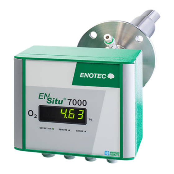
- Page 1 Installation and Operation Manual Transmitter Probe ENSITU 7000 ® Version 04 Doc.-ID: ENS_13062019-EN...
- Page 2 ENOTEC probes include the zirconium oxide sensor which has a gas-tight seal made by using a special process and technique developed by ENOTEC. This leads to a considerably increased service life compared to "glued or cemented"...
-
Page 3: Table Of Contents
Probe components ......31 3.2.1 Search for available analyzers ... 12 D Warranty 32 3.2.2 Pair with the Analyzer ......12 ® 3.2.3 Connect with the ENSITU 7000 Index 33 Analyzer ..........13 3.2.4 Enter the Pin Code ......14 3.3 ... -
Page 4: 1 System Description
Manufacturer supply Isolation Customer supply Duct wall Customer supply Power supply 48V DC , 5A max.- Optional: Power adapter from ENOTEC Max. cable length, 50 m Input and output signals (analog and digital) Test air / test gas in Doc.-ID: ENS_13062019-EN... - Page 5 Cable with plug. Max. cable Customer supply length = 50 m Power supply 48V DC, 5A max. Optional: Power adapter from ENOTEC Max. cable length = 50 m Input and output signals (analog and digital) Test air / test gas in...
-
Page 6: Measuring Principle
System Description ® Installation and Operation Manual - ENSITU 7000 Measuring Principle ® The ENSITU 7000 O probe is installed in a duct to measure O in non-combustible process gases and is coupled with an electronic unit for voltage and signal processing. The oxygen sensor is at the tip of the probe and is regulated to 800 °C and works on the zirconium oxide principle of measurement. -
Page 7: Disruption Of The Process
(heater, thermocouple and sensor) and reduces their product life. ENOTEC will not accept any responsibility for resultant damage. Storage instructions ENOTEC equipment and spares are to be stored in a dry and ventilated environment. Paint fumes, silicone sprays, etc. must be avoided in the storage environment. Name Plates The name plate contains information about the voltage, the nominated current, frequency, protection class and serial number. -
Page 8: 2 Installation
Before cutting a hole in the flue gas duct, make sure that the inside of the duct has enough space for probe installation and that no fly ash is blown out nearby or any obstacles are in the way. ENOTEC recommends installing the probe horizontally (-3 ° to - 5 °) for fastest possible response times. Transmitter probe... -
Page 9: Adjusting The V-Shield
Figure 4 - Adjustment of the abrasion shield Mounting of the Probe Insulation (customer supply) Counter flange (optional ENOTEC supply) Flange gasket Bolts Electronic unit Figure 5 - Mounting of the Probe – for dimensions, see chapter B. Doc.-ID: ENS_13062019-EN... -
Page 10: Connection Of The Probe Plug For Detached Electronics
Installation ® Installation and Operation Manual - ENSITU 7000 Connection of the probe plug for detached electronics Contact Polarity Description Probe heater 1, 2 Probe data board Thermocouple sensor Probe heater 6, 7 Probe data board Thermocouple sensor Figure 6 - Probe plug connection for detached electronics. See Figure 2 for configuration and chapter 0 for cable specifications. -
Page 11: Wiring Diagram Of The Electronic Unit
® Installation Installation and Operation Manual - ENSITU 7000 Wiring Diagram of the Electronic Unit ® ENSITU 7000 Figure 8 - Wiring diagram of the Electronic Unit 48 V DC 5A Power supply 4-20 mA Sink analog output 4-20 mA Source 24V DC = Active zero point calibration Shield... -
Page 12: Test Gas Connection / Reference Air Ports
Installation ® Installation and Operation Manual - ENSITU 7000 Test gas connection / reference air ports Figure 9 - Overview of test gas connection / reference air ports The test gas connection is equipped with a check valve with 1/4" parker connection for 1 or 2-point calibration purposes. See chapter 3.6 for the calibration procedure. -
Page 13: 3 Software And Analyzer Control
ENSITU 7000 has no interface to interact with and can be controlled via smartphone or tablet running the Android operating system over a Bluetooth connection using the ENOTEC Remote app. The interface language of the app will be the system language on the Android smart device. -
Page 14: Establish A Connection
7000 analyzer will appear in the list of Bluetooth enabled devices on your smart device. Tap on the analyzer name. The blue LED of the analyzer will now blink. Tap the back arrow to return to the ENOTEC Remote app. ® Should the ENSITU... -
Page 15: Connect With The Ensitu 7000
FAQ and troubleshooting. Cloud and other settings. Cloud storage is not hosted by ENOTEC GmbH. Users of the ENOTEC Remote app can find help for the standalone setup of the cloud at http://www.owncloud.org. QR code reader to transfer sensor parameters to the analyzer. -
Page 16: Enter The Pin Code
Save all analyzer information on the smart device or in a private cloud, send the file electronically. Service menu (hidden in normal state, contact ENOTEC). Disconnect from the analyzer. Appears when a warning occurs. Tap for details. Appears when an error occurs. Tap for details. -
Page 17: Change Access Level
Info The ENOTEC Remote app can save all relevant analyzer and process information to an HTML file. This file can be saved locally or be sent to an ENOTEC service point for analysis. Enter the „Archive“ menu. Tap “CREATE SYSTEM PROTOCOL” and... -
Page 18: O 2 Sensor Calibration
Software and Analyzer Control ® Installation and Operation Manual - ENSITU 7000 Sensor Calibration Info To achieve a higher accuracy, a calibration can be carried out. An O sensor calibration can be started as soon as high gas (e.g. instrument air or ambient air, 20.95 vol. % O ) or low gas (certified bottled test gas, e.g. -
Page 19: 4 Initial Operation
Blinks during heating phase. Green Lit when measurement is valid Blue Lit when an ENOTEC Remote connection is active Lit when an error has occurred and the error has not been rectified Blinks when an error has occurred, has been rectified ®... -
Page 20: 5 Service And Maintenance
Service and Maintenance ® Installation and Operation Manual - ENSITU 7000 Service and Maintenance Warning Hot Surface The probe may only be removed with heat-insulated gloves. Before removing the probe, always switch off the supply voltage to the electronics. After removal, store the probe in a safe, protected place and wait until it has cooled down below 35 °C/ 95 °F. -
Page 21: Test Air Supply With Instrument Air
® Service and Maintenance Installation and Operation Manual - ENSITU 7000 5.3.2 Test air supply with instrument air Instrument air (ISO 8573-1 class 2) Pressure reducer Flow meter (150 … 180 l/h) Figure 23 - Test air supply using instrument air 5.3.3 Test gas / Test air supply (certified test gas) Test gas bottle... -
Page 22: Exchange Of The Probe Inner Part
Service and Maintenance ® Installation and Operation Manual - ENSITU 7000 Exchange of the probe inner part Info The probe inner part SIK-700X needs to be replaced in the event that a breakage or defect occurs in any of the following parts: Sensor signal wire, thermocouple, heater or ceramic rod. Unhinge the clamps holding the electronics to the coupling. -
Page 23: Replacing The Filter
® Service and Maintenance Installation and Operation Manual - ENSITU 7000 Replacing the Filter 5.6.1 Remove the old Filter Clamp the filter head in a vice. Free the filter by using a hammer and a metal extension to force the filter from the filter head Remove all old filter remnants... -
Page 24: 6 Error Codes
2.00 mA) and non-active errors (fault has been eliminated but not confirmed - blinking red error LED). For error codes, which are not described in the table below, please contact ENOTEC. These errors cannot be remedied by the operator. - Page 25 The O sensor heater is switched off. An error reset error. can be carried out using the ENOTEC REMOTE app in order to restart the heating process. Probe set point temp. not reached. Possible causes: F2 fuse defective, ad connection between...
-
Page 26: 7 Troubleshooting
Electronic unit is defective. mA output is Measure the mA output on the strip terminal. Set a incorrectly parameterized mA output value in the ENOTEC REMOTE app (mA check) and measure the current at terminal block X2 on terminal point 2 and 3. -
Page 27: A Technical Specifications
® Technical Specifications Installation and Operation Manual - ENSITU 7000 Technical Specifications Technical specifications - KES-700X KES-7000 - 313 mm Insertion depth: KES-7001 - 536 mm KES-7002 - 996 mm Ceramic / Basalt / Sintered metal Filter: (Filter head with V-Shield) Test gas shut-off: Check valve IP code:... -
Page 28: Technical Specifications - Electronics Unit
M16: 5 - 9,5 mm Ø Maximum distance probe <=> 30 m external 48 VDC power supply: Operation: ENOTEC Remote app (multilingual), digital input Measured values, parameter settings, calibration, error Features: diagnostics, logging, data transmission * Other specifications available upon request.*... -
Page 29: Technical Specifications
1,5 mm² Temperature range: -40 °C to + 80 °C (fixed installation) Cable for power supply Number of cores: Cable diameter: 2,5 mm² Temperature range: -40 °C to + 80 °C (fixed installation) For cable recommendations, please contact ENOTEC. Doc.-ID: ENS_13062019-EN... -
Page 30: B Dimensional Drawings
Dimensional Drawings ® Installation and Operation Manual - ENSITU 7000 Dimensional Drawings Dimensional drawings of the KES-700X probes Figure 29 – KES-7001 dimensional drawing Figure 30 – KES-7001 dimensional drawing Doc.-ID: ENS_13062019-EN... -
Page 31: Counter Flange Adp-7000
® Dimensional Drawings Installation and Operation Manual - ENSITU 7000 Figure 31 – KES-7002 dimensional drawing Counter flange ADP-7000 Figure 32 – ADP-7000 counter flange Doc.-ID: ENS_13062019-EN... -
Page 32: Kes-700X Probe Inner Parts
Dimensional Drawings ® Installation and Operation Manual - ENSITU 7000 KES-700X Probe inner parts Figure 33 – SIK-7000 probe inner part Figure 34 – SIK-7001 probe inner part Figure 35 – SIK-7002 probe inner part Doc.-ID: ENS_13062019-EN... -
Page 33: C Spare Parts
® Spare Parts Installation and Operation Manual - ENSITU 7000 Spare Parts Probe components Figure 36 – ENSITU 7000 components No. Part Part No. Electronic unit ENS-70000000001000 Probe tube MSR-700X Coupling 0-X-000651 pin insert 0-X-000699 Probe inner part SIK-700X Sensor... -
Page 34: D Warranty
ENOTEC will not accept any responsibility for such damages. Suitable tools must be used when installing and commissioning ENOTEC products and systems. If any damage is caused due to the use of unsuitable tools, ENOTEC will not accept any responsibility for damages. -
Page 35: Index
Replacing the Filter D S Dimensional Drawings Save system protocols Disruption of the Process Screen Overview Software E Storage ENOTEC Remote System Overview Error Codes System Protocols Exchange fuses Exchange of Probe Inner Parts T Technical Specifications I Electronics Initial operation... - Page 36 Manufacturer ENOTEC GmbH Höher Birken 6 D-51709 Marienheide Germany Tel.: +49 (0) 2264 / 45 78 – 0 Fax: +49 (0) 2264 / 45 78 – 30 E-Mail: info@enotec.com Internet: www.enotec.com...
Need help?
Do you have a question about the ENSITU 7000 and is the answer not in the manual?
Questions and answers