
Related Manuals for Enotec SILOTEC 8000


Summary of Contents for Enotec SILOTEC 8000
- Page 1 Installation and Operation Manual ® SILOTEC 8000 Analyzer System for Silo Monitoring Version 03 for software version: 4.13 Doc.-ID: SILOTEC_11022020_EN...
- Page 2 The MXP sensor measures not only CO but also all other combustibles (hydrocarbons and hydrogen). All ENOTEC instruments are thoroughly tested in the factory and are subject to a strict ISO9001 Quality Assurance Procedure. ®...
-
Page 3: Table Of Contents
System Checks ..........33 CAL MENU ............34 System Overview of the SILOTEC 8000 ..... 4 Measuring Principles ........... 5 4.4.1 Calibration Menu - Display Overview ....34 ... -
Page 4: System Description
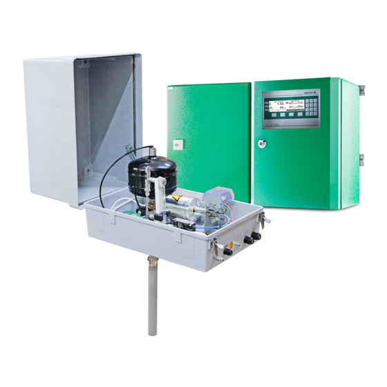
System Description ® System Overview of the SILOTEC 8000 Figure 1 - System overview of the SILOTEC 8000 analyzer system Safe Area Electronic unit SME5 (IP66) Max. ambient temp.: -20 °C to +55 °C (-4 °F to + 131 °F) -
Page 5: Measuring Principles
If a smoldering fire occurs in the silo, carbon monoxide is formed by the consumption of oxygen. SILOTEC 8000 can detect this smoldering fire immediately on the basis of the increase in the CO concentration and the decrease in the content, and suitable safety measures can be taken. -
Page 6: Safety Hazards
Storage instructions ENOTEC equipment and spares are to be stored in a dry and ventilated environment at temperatures between -40 °C to +80 °C (-40 °F to 176 °F)moisture?. Paint fumes, silicone sprays, etc. must be avoided in the storage environment. -
Page 7: Name Plates
System Description Installation and Operation Manual - SILOTEC 8000 Name Plates The name plate contains information about the line voltage, the nominated current, frequency, protection class, year of manufacture, serial number, order number and system order code. The system order code refers to information which is detailed in the system test report and supplied with the system. -
Page 8: System Description - Contents Of Grp Housing
System Description Installation and Operation Manual - SILOTEC 8000 System description – Contents of GRP housing Abb. 3 – Contents of the GRP housing Injector 2-2-way solenoid valve for purging Flow meter with alarm module 3-2-way solenoid valve for measuring... -
Page 9: Installation
Installation Installation and Operation Manual - SILOTEC 8000 Installation Warning The electronic unit does not have a line voltage main switch. The line voltage power supply requires a switch or breaker. The line voltage switch/fuse/breaker must be in accordance with the local technical standards and should be in close proximity to the electronic unit and must be identifiable as such. -
Page 10: Installation Of Probe Signal Cable Fep-0007/8
Shield of 1, 2 & 3 bare FEP-0008 (armored) white/ white/ measuring cell 4 x 0,75 mm red/ red Warning Only use ENOTEC probe cables, as the thermocouple cables 2 and 3 are compensating cables and are necessary for correct measurement. Doc.-ID: SILOTEC_11022020_EN... -
Page 11: Access To The Terminals
Installation Installation and Operation Manual - SILOTEC 8000 Access to the Terminals Warning Before removing the terminal covers, switch off the mains voltage to the system. Switch the mains voltage on only after attaching the terminal cover. After the installation has been completed, live parts may no longer be accessible. -
Page 12: Wiring Diagram Of The Electronic Unit
Installation Installation and Operation Manual - SILOTEC 8000 Wiring diagram of the Electronic Unit Figure 7 - Wiring diagram of the electronic unit A Ferrite sleeves (Enclosed) Analogue output cable (customer) B Power supply cable (customer) Status signal cable (customer) -
Page 13: Wiring Diagram Of The Silotec 8000
Installation Installation and Operation Manual - SILOTEC 8000 Wiring Diagram of the SILOTEC 8000 Figure 8 - Wiring diagram of the SILOTEC 8000 Doc.-ID: SILOTEC_11022020_EN... - Page 14 Installation Installation and Operation Manual - SILOTEC 8000 Figure 9 – SILOTEC 8000 digital and analog signals Doc.-ID: SILOTEC_11022020_EN...
- Page 15 Installation Installation and Operation Manual - SILOTEC 8000 Figure 10 - SILOTEC 8000 solenoid valves, flow meters Doc.-ID: SILOTEC_11022020_EN...
-
Page 16: Gas Plans
Installation Installation and Operation Manual - SILOTEC 8000 Gas Plans Figure 11 - SILOTEC 8000 standard gas plan Doc.-ID: SILOTEC_11022020_EN... - Page 17 Installation Installation and Operation Manual - SILOTEC 8000 Figure 12 - SILOTEC 8000 gas plan with options Doc.-ID: SILOTEC_11022020_EN...
-
Page 18: Installation Of The Probe
Installation Installation and Operation Manual - SILOTEC 8000 Installation of the analyzer The temperature, pressure and all other process conditions must be in accordance with the specification. Leave enough space for insertion/removal of the probe and ensure access to the measuring probe and/or GRP housing. -
Page 19: Electrical Connections Of The Cuvette
Installation Installation and Operation Manual - SILOTEC 8000 2.10 Electrical Connections of the Cuvette Info The Probe Signal Cable FEP-0007/8 has to be connected to the terminal board in the probe terminal box. Do not connect the shield here. Figure 14 - Electrical connections of the probe connection box SIL-KES-0001 2.11... -
Page 20: Preparation Of The Pneumatic Cable
Installation Installation and Operation Manual - SILOTEC 8000 2.12 Preparation of the pneumatic Cable Pneumatic tubing of the pneumatic cable FEP-0002 Clamp ring Support sleeve Both, the pneumatic tubing for the reference air (blue) and the test gas (green) have to be prepared... -
Page 21: Pneumatic Connections Of Electronic Units
Installation Installation and Operation Manual - SILOTEC 8000 2.14 Pneumatic Connections of Electronic Units Figure 17 - Bottom view of SME-53 with pneumatic unit Tube Description 1/4“ Testgas in Testgas out 1/4“ Instrument air in 1/4“ Reference air out 1/4“... -
Page 22: Initial Operation
Switch on the line voltage to the system. After a short power up information, the user is prompted to Select language, set the System date, System time, enter a TAG number and ENOTEC REMOTE code (only if option ENOTEC REMOTE is factory activated) and the cable length. -
Page 23: Display - Probe Heating Phase
Initial Operation Installation and Operation Manual - SILOTEC 8000 Display - Probe Heating Phase The probe heating phase begins with the heating up of the O sensor. After this is concluded, the sensor begins its heating up phase. TAG number... -
Page 24: Status Leds
Initial Operation Installation and Operation Manual - SILOTEC 8000 Status LEDs Softkey Symbols Alarm, - orange - is lit when an Moves the selection one position upwards alarm has been activated (e.g. O limit alarm) Moves the selection one position down-... -
Page 25: Software Overview And Explanations
Software Overview and Explanations Installation and Operation Manual - SILOTEC 8000 Software Overview and Explanations Software Overview - SYS-MENU SYS-MENU System Information Actual measured values measured value (% O ) {may be ppm} -mA output 17A/B (mA) sensor input (mV) - Page 26 Software Overview and Explanations Installation and Operation Manual - SILOTEC 8000 Calibration results (cont.) ~~ Test gas data ~~ Test air (20,95 % O Test air (0 ppm CO Test gas (e.g. 2,1 % O Test gas (e.g. 1000 ppm CO)
- Page 27 Software Overview and Explanations Installation and Operation Manual - SILOTEC 8000 limit alarms Limit alarm 1 (O )(OFF/ON) ♦ at } visible when set to "ON" ♦ hysteresis Limit alarm 2 (CO )(OFF/ON) ♦ at } visible when set to "ON"...
- Page 28 Software Overview and Explanations Installation and Operation Manual - SILOTEC 8000 System clock/TAG number System date (jjjj-mm-tt) System time (hh:mm:ss) ENOTEC REMOTE settings (optional) } Visible when ENOTEC REMOTE interface is activated ENOTEC REMOTE (ON/OFF) Passkey (8 digit code) } Visible when ENOTEC REMOTE is ON...
-
Page 29: Software Explanations - Sys-Menu
Software Overview and Explanations Installation and Operation Manual - SILOTEC 8000 Software Explanations - SYS-MENU 4.2.1 Measuring Ranges (Scaling) The O Measuring range is linearly scaled and converted to a linear current output (0/ 4-20 mA). The parameter „O Measuring range from“... -
Page 30: Co E Measuring Ranges (Scaling)
Software Overview and Explanations Installation and Operation Manual - SILOTEC 8000 4.2.6 Measuring Ranges (Scaling) The CO Measuring range is linearly scaled and converted to a linear current output (0/ 4-20 mA). The parameter „ CO Measuring range from“ is the start value of the CO range, leading to an output of 4,00 mA. -
Page 31: Enotec Remote
The device configuration can also not be altered. Range limits the transmission power of the ENOTEC REMOTE module. Maximum = 100m, medium = 10m, short = 1m. The actual possible range may vary due to structural factors and the reception strength of the Smartphone/Tablet. -
Page 32: Language
4.2.18 Service The service functions are password protected and are only accessible by trained service personnel. These functions are protected with a code, different to the system code. Please contact ENOTEC. Doc.-ID: SILOTEC_11022020_EN... -
Page 33: System Checks
Software Overview and Explanations Installation and Operation Manual - SILOTEC 8000 System Checks + CO Sensor checks Source: Test air sensor .. mV = .. % sensor .. mV = .. ppm Flow rate .. l/h Source: Test gas sensor ... -
Page 34: Cal Menu
Software Overview and Explanations Installation and Operation Manual - SILOTEC 8000 CAL MENU CAL MENU 1 point calibration, O 2 point calibration, O 1 point calibration, CO 2 point calibration, CO 1 point calibration, O + CO 2 point calibration, O + CO 4.4.1... -
Page 35: 1-Point Calibration (O And/Or Co ) (Manual)
Software Overview and Explanations Installation and Operation Manual - SILOTEC 8000 Info The oxygen concentration in test air needs not be entered as it is a known constant (20,95 % O During calibration, entry of the test gas concentration value takes place after test gas has been applied. -
Page 36: Service And Maintenance
Service and Maintenance Installation and Operation Manual - SILOTEC 8000 Service and Maintenance Exchange fuses Warning De-energize the system first! Abb. 29 Position of the fuses fuse system voltage ampere nominal voltage characteristic Size 115 / 230 V AC 0.5 A... -
Page 37: Position Of The Adjustment Valves
Service and Maintenance Installation and Operation Manual - SILOTEC 8000 Position of the adjustment valves Figure 30 - Terminal cover of the SME-53 electronic unit showing the position of the test air valve Adjusting Flow Rate (SME-54 19” rack) With systems in 19“ racks the test air quantity can be adjusted at the back of the electronic unit. -
Page 38: Adjusting The Sample Gas Extraction Rate
Service and Maintenance Installation and Operation Manual - SILOTEC 8000 Adjusting the sample gas extraction rate The extraction rate must be set to 40 - 80 l / h. Use the pressure reducer for a preliminary adjustment. Use the needle valve... -
Page 39: Replace The Probe Inner Part
Service and Maintenance Installation and Operation Manual - SILOTEC 8000 Pull the tabs of the cover profile slightly upwards and remove the cover profile. Loosen the screws of the cuvette holder Figure 33 – Loosen the cuvette mounting ... -
Page 40: Replace The Probe Tube With O Sensor
Service and Maintenance Installation and Operation Manual - SILOTEC 8000 5.6.2 Replace the probe tube with O sensor Carry out the procedures as described in chapter 5.6 to remove the measuring cuvette. Remove the inner part of the probe as described in... -
Page 41: Seal The Co Sensor Guide Tube
Tightening torque: 250 Nm. Blow-back (optional) The SILOTEC 8000 system has an optional blow-back module. The option includes a 4 l purge tank filled with instrument air at operating pressure, two timer relays controlling the purge process and a solenoid valve. During blow-back, the entire tank volume is flushed into the silo through the sample probe / filter, while the gas path to the cuvette is closed. -
Page 42: Relay Outputs / Functions And Correlation
Service and Maintenance Installation and Operation Manual - SILOTEC 8000 Relay Outputs / Functions and Correlation The relay contacts are designed for 24V and 1A AC/DC = (Exception: probe valve) Relay Contact Function System error* Normally closed Signals operation-critical errors... -
Page 43: Status Messages
Status Messages Installation and Operation Manual - SILOTEC 8000 Status Messages Error Messages Error Relay signal Description Message contact output 2.00 mA, System The error can occur at any time and signalizes a failure of one of the Hardware when not error, electronic components. - Page 44 If the error occurs again, switch the system on and off. If the error n error otherwise persists after restarting the system, contact an ENOTEC service point. The error can occur at any time and signals a short circuit either by CO sensor heating or within the connection between the electronic unit and CO sensor.
-
Page 45: Alarm Messages
Status Messages Installation and Operation Manual - SILOTEC 8000 Alarm Messages Error Relay Description Message contact limit Limit alarm 1 alarm 1, Possible Cause: Over or under range of the O limit alarm. open limit Limit alarm 2 alarm 2, Possible Cause: Over or under range of the limit alarm. -
Page 46: Troubleshooting
Troubleshooting Installation and Operation Manual - SILOTEC 8000 Troubleshooting Unsteady, widely varying measuring value (O Possible reasons Procedure Intermittent contact caused by wire breakage Eliminate bad/loose contact Intermittent contact inside the probe - internal mV connection display remains at the end of the measuring range or is higher than expected... - Page 47 Troubleshooting Installation and Operation Manual - SILOTEC 8000 Local Displays correct, Output not correct Possible reasons Procedure Electronic unit is defective Check measuring range. Check whether the current value is outside the measuring range Electronic unit is defective Measure the mA output on the strip terminal.
-
Page 48: Technical Data
Technical Data ® Installation and Operation Manual - SILOTEC 8000 Technical Data Technical Specifications SME-53 Electronic Unit Housing: sheet steel powder coated; RAL6029 (GRP version optional) (SME-54, 19” rack optional) IP Code: Safe Area Housing: IP66 GRP cabinet: IP66 19“ housing: IP20 Display: LC Dot Matrix 240 x 64 - LED backlit... -
Page 49: Technical Specifications - Probes
Technical Data ® Installation and Operation Manual SILOTEC 8000 Technical Specifications - Probes Process gas temperature: SIL-KES-0001: up to 100 °C (212 °F) Immersion depth: approx. 500 mm Measuring principle: Zirconium oxide for O MXP for CO Process gas pressure: ±50 mbar (±0.725 PSIG) to atmospheric pressure Ambient temperature: -20 °C to +55 °C (-4 °F to 131 °F) other on request... -
Page 50: Requirements Of The Gas Supply
Technical Data ® Installation and Operation Manual - SILOTEC 8000 Requirements of the Gas Supply The analyzer system uses the connected instrument air continuously for the supply of reference air, and during calibration and system test respectively, for the supply of test air (test gas 1). Test gas / Air quality According to ISO 8573-1 Class 2 Particle size:... -
Page 51: Dimensional Drawings
Dimensional drawings ® Installation and Operation Manual SILOTEC 8000 Dimensional drawings Electronic units dimensions Figure 42 - Dimensions (mm) of the electronic unit SME-53 Figure 43 - Dimensions (mm) of the electronic unit in 19’’ rack - SME 54 Figure 44 - Dimensions (mm) of the Optional SME-56 GRP Cabinet Doc.-ID: SILOTEC_11022020_EN... -
Page 52: Probe Dimensions
Dimensional drawings ® Installation and Operation Manual - SILOTEC 8000 Probe dimensions Probe inner part SIK-5001 Figure 45 - SIK-0501 probe inner part Doc.-ID: SILOTEC_11022020_EN... -
Page 53: Silotec 8000 Spare Parts Overview
SILOTEC 8000 spare parts ® Installation and Operation Manual SILOTEC 8000 SILOTEC 8000 spare parts Overview Figure 46 – SILOTEC 8000 spare parts Description Article number Power supply solenoid valves Alarm module flow meter 0-P-001350 Flow Meter 0-P-001349 Non-return valve throttle (optional) -
Page 54: Mounting Plates Of Sme-53 Electronic Unit
SILOTEC 8000 spare parts ® Installation and Operation Manual - SILOTEC 8000 Mounting Plates of SME-53 Electronic Unit Mounting Plate 1 Test gas and reference air unit for instrument Transformer primary 2*115V, sec. TRA-0017 115V Test gas solenoid valve P01 for SME53... -
Page 55: Display Board
SILOTEC 8000 spare parts ® Installation and Operation Manual SILOTEC 8000 Mounting Plate instrument air, version A and version 1 0-P-000780 Pressure regulator with two chokes Version 1 0-P-001369 Pressure regulator with one choke Version A TRA-00017 Toroid transformer 2x115V;sec.115V/330VA... -
Page 56: Warranty
E N O T E C W A R R A N T Y ENOTEC warrants that systems manufactured and sold by it will, upon shipment, be free of defects in workmanship or material. Should any failure to conform to this warranty become apparent during the relevant warranty periods, ENOTEC shall, upon prompt written notice from the purchaser, correct such nonconformity by repair or replacement of the defective part or parts. -
Page 57: Declaration Of Conformity
ENOTEC GmbH Höher Birken 6 51709 Marienheide Germany Tel.: +49 2264 45 78-0 Product / Produkt: SILOTEC 8000 Description / Beschreibung: CO analyzer system for silo monitoring Analysesystem zur Siloüberwachung Relevant EU directives / relevante EU Richtlinien: 2014/34/EU, ATEX directive / ATEX-Richtlinie... -
Page 58: Index
W limit value 1............41 limit value 2............41 Warranty ............55 Wiring diagram ..........12 Wiring Diagram of the SILOTEC 8000 .... 13 M Mains voltage ..........47 Measuring Principle ........... 5 Menu Explanations Time per test gas apply ........29 N ...
Need help?
Do you have a question about the SILOTEC 8000 and is the answer not in the manual?
Questions and answers