
Related Manuals for VWR avantor 600 Series


Summary of Contents for VWR avantor 600 Series
- Page 1 Instruction manual Microscope VisiScope ® Series 600 Model European Catalogue Number IT600 FLD 630-3267 VERSION: 1.0 ISSUED: 28/02/2021...
- Page 2 LEGAL ADDRESS OF MANUFACTURER Europe VWR International bv Researchpark Haasrode 2020 Geldenaaksebaan 464 B-3001 Leuven + 32 16 385011 be.vwr.com UK Importer VWR International Ltd Hunter Boulevard, Magna Park Lutterworth, Leicestershire, LE17 4XN uk.vwr.com Country of Origin Italy vwr.com | Instruction manual...
-
Page 3: Table Of Contents
9.7 Coarse focus tension adjustment 17. Repair and maintenance 9.8 Stage and stage inserts 18. Technical service 9.9 Illumination column 19. Warranty 9.9.1 Using colour filters 20. Compliance with local laws and regulations 9.9.2 Tilting the condenser holder Disposal Instruction manual | vwr.com... -
Page 4: Warning
Users should observe all safety regulations of the region. The equipment has acquired the CE safety label. However, users have full responsibility to use this equipment safely. Please follow the guidelines below, and read this manual in its entirety to ensure safe operation of the unit.. vwr.com | Instruction manual... -
Page 5: Package Contents
Power cord NOTE: The IT600FLD is fully configurable in the number and type of objectives. Therefore, the objectives are not shown in this diagram even though they are included in the configuration. Instruction manual | vwr.com vwr.com | Instruction manual... -
Page 6: Unpacking
The following chart is an illustrated glossary of the symbols that are used in this manual. CAUTION This symbol indicates a potential risk and alerts you to proceed with caution ELECTRICAL SHOCK This symbol indicates a risk of electrical shock. vwr.com | Instruction manual... -
Page 7: Instrument Description
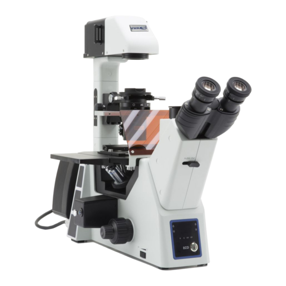
Light path Selector lever Main switch Led centering knobs Microscope body X-y stage movement knobs Field stop lever Transmitted light intensity indicator Objective Condenser Centering screws Stage Aperture stop lever Eco button Brightness adjustment knob Stage plate (transmitted light) Instruction manual | vwr.com... - Page 8 Opposite side Diffusion filter Fluorescence led lamp housing Fluorescence filter selector Brightness adjustment knob (reflected light) Fluorescence filter indicator Reflected light intensity indicator UV shield vwr.com | Instruction manual...
-
Page 9: Microscope Assembling
The mechanical stage must be installed on the right side of the microscope. Installing the stage extension: screw the bolts on to the extension, then mount the extension from below the stage. (Fig. 4) FIGURE 4 Instruction manual | vwr.com... -
Page 10: Installing Stage Inserts
Install the stage insert in the stage opening. (Fig. 6) FIGURE 6 Install the holder in the mechanical stage. (Fig. 7) FIGURE 7 Multi well plates can be directly inserted in the mechanical stage. (Fig. 8) FIGURE 8 vwr.com | Instruction manual... -
Page 11: Installing Eyepieces
(Fig. 11) FIGURE 11 Insert the Phase contrast slider (or the DF slider) into the condenser, printed face up. (Fig. 12) Pull the slider into the “SL” position, to the click stop. FIGURE 12 Instruction manual | vwr.com... -
Page 12: Mounting The Fluorescence Lamp Housing
(Fig.14) FIGURE 14 Tighten the locking screw using the provided Allen screwdriver. (Fig.15) FIGURE 15 Connect the cable of the lamp housing to the connector in the back side of the microscope. (Fig.16) FIGURE 16 vwr.com | Instruction manual... -
Page 13: Connecting The Power Cord
Plug the power cord into the mains socket. Check for a safe connection. Please use the provided power cord. If lost or damaged, please refer to qualified service. Connect the power cord to a grounded power supply only. FIGURE 19 Instruction manual | vwr.com... - Page 14 Aperture diaphragm Adjust field and aperture iris diaphragms Field diaphragm Nosepiece Insert desired objective for the observation and focus the spec- imen Coarse and fine focusing knobs Transmitted light adjustment dial Adjust light intensity Begin observation vwr.com | Instruction manual...
-
Page 15: Use Of The Microscope In Brightfield (Transmitted Light)
The graduation on the interpupillary distance indicator 4, pointed by the spot “.” on the eyepiece holder, shows the distance between the operator’s eyes. (Fig. 23) The range of the interpupillary distance is 48-75 mm. FIGURE 23 Instruction manual | vwr.com... -
Page 16: Diopter Adjustment
/ TV port. Move the selector 2 to the left (In) or to the right (Out) to distribute the light. (Fig. 27) POSITION LIGHT 100% TV 100% EYEPIECES FIGURE 27 vwr.com | Instruction manual... -
Page 17: Coarse Focus Tension Adjustment
Holder for Terasaki and Petri diameter 65 mm (provided with the microscope) Holder for slide and Petri diameter 54 mm (provided with the microscope) Holder for 2+2 slides Holder for Utermöhl-Chamber (holder for Petri diameter 54 mm needed) Instruction manual | vwr.com... -
Page 18: Illumination Column
(Fig. 32) Put the specimen on the stage and begin observation. Once terminated the observation return the illumination column to its original position and lock the knob. FIGURE 31 FIGURE 32 vwr.com | Instruction manual... -
Page 19: Centering The Led
Slide the phase slider to the “SL” position 1 (Fig. 35) Engage the 10x objective, place the specimen on the stage and adjust approximate focusing. FIGURE 35 Use the field diaphragm (FS) selector lever 2 (Fig. 36) to close the field diaphragm. FIGURE 36 Instruction manual | vwr.com... -
Page 20: Effect Of The Field Diaphragm
2 to about 70%-80% of the objective’s N.A. (Fig. 40). If necessary, remove one eyepiece and, looking into empty eyepiece sleeve, adjust the condenser’s ring in order to obtain an image like the one in Fig. 41. FIGURE 40 vwr.com | Instruction manual... - Page 21 70% and 80% of DIAPHRAGM 30-20% the numerical aperture of the objective. In phase contrast (PH) or in darkfield (DF), the aperture diaphragm must be fully opened by operating on the AS lever. FIELD OF VIEW FIGURE 41 Instruction manual | vwr.com...
-
Page 22: Use Of The Microscope In Phase Contrast (Transmitted Light)
Use the CT to focus on the slider phase ring image 1 (bright) and the objective phase ring image 2 (dark). If phase ring image is not sharp, adjust the CT until you can see a clear image of the phase ring. (Fig. 44) FIGURE 44 vwr.com | Instruction manual... - Page 23 The phase ring may need re centering during and after observation of very thick specimens. The phase ring may show an apparent misalignment if the cover glass is not flat. FIGURE 45 FIGURE 46 Instruction manual | vwr.com 23...
-
Page 24: Use Of The Microscope In Darkfield (Transmitted Light)
0.40. With higher N.A. the darkfield effect cannot be achieved FIGURE 47 because of the condenser N.A. Slider position Empty Meaning empty hole darkfield ring Application Brightfield observation Darkfield observation with 4x,10x, 20x objectives vwr.com | Instruction manual... -
Page 25: Summary Of Fluorescence Observation Procedures (Reflected Light)
Diopter adjustment ring Adjust diopters Field diaphragm Adjust field iris diaphragm Nosepiece Insert desired objective for the observation and focus the spec- Coarse and fine focusing knobs imen Reflected light adjustment dial Adjust light intensity Begin observation Instruction manual | vwr.com 25... -
Page 26: Use Of The Microscope In Fluorescence (Reflected Light)
495 nm 585 nm Emission filter 420lp nm 525/50 nm 645/75 nm Application Autofluorescence FITC: fluorescent antibodies Rhodamine, TRITC: fluorescent antibodies DAPI: staining for DNA Achridine orange: DNA, RNA Propidium Iodide: DNA, RNA Hoechst: chromosomes Auramine vwr.com | Instruction manual... -
Page 27: Centering The Field Diaphragm (Fs)
Move the filter cube selector to the desired filter position. Adjust the reflected light intensity. To obtain the proper specimen observation, adjust the transmitted light intensity, in order to modulate the fluorescence intensity with the phase contrast intensity. Instruction manual | vwr.com... -
Page 28: Microphotography
To calculate the magnification of the camera: objective magnification * camera magnification * lens magnification. If using an SLR camera, mirror movement may cause the camera to vibrate. We suggest lifting the mirror, using long exposure times and a remote cord. vwr.com | Instruction manual... -
Page 29: Troubleshooting
To a certain extent it is due to achromatic objectives features proper position Stray light entering in the microscope through eyepieces or Bright spots appear on the image Cover eyepieces and viewfinder with a dark cloth camera viewfinder Instruction manual | vwr.com 29... -
Page 30: Repair And Maintenance
Product in its local environment. VWR will not be held liable for any related omission or for not Note: ethanol and ether are highly flammable liquids. Do obtaining the required approval or authorization, unless any not use them near a heat source, near sparks or near electric refusal is due to a defect of the product. -
Page 31: Disposal
By doing so, you will help to conserve natural and environmental resources and you will ensure that your equipment is recycled in a manner that protects human health. Thank you Instruction manual | vwr.com... - Page 32 (international) info.no@vwr.com Leicestershire info.fr@vwr.com LE17 4XN + prix appel Tel.: +44 (0) 800 22 33 44 * 0,18 € TTC/min uksales@vwr.com GO TO VWR.COM FOR THE LATEST NEWS, SPECIAL OFFERS AND DETAILS FROM YOUR LOCAL VWR SUPPORT TEAM ©2021 ZPROVWRI32623-EN...
Need help?
Do you have a question about the avantor 600 Series and is the answer not in the manual?
Questions and answers