
Subscribe to Our Youtube Channel
Related Manuals for Aybey Elektronik ALYA


Summary of Contents for Aybey Elektronik ALYA
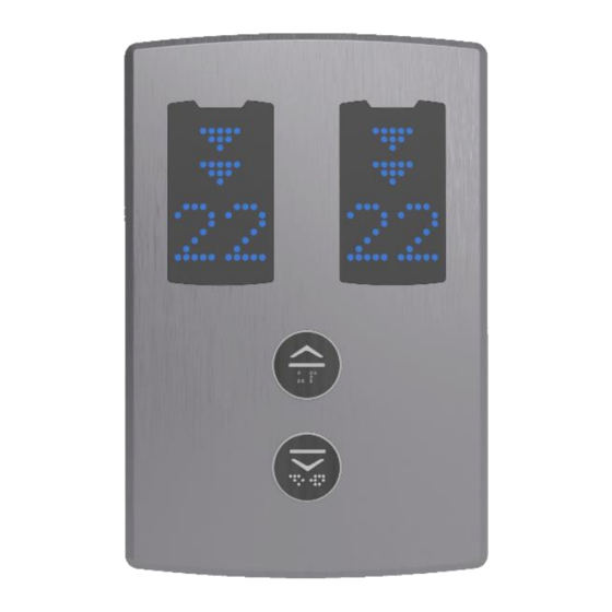
- Page 1 APPENDIX-3 LANDING OPERATION PANEL INSTALLATION ALYA SERIAL COMMUNICATION DUPLEX LOP INSTALLATION MANUAL Document Name : Duplex ALYA User and Installation Manual Display Type : Dot Matrix Led Document Code : -- Document Version : 1.0...
- Page 2 1- Mechanical Installation 1.1 Open the front cover by pressing the spring mechanism at the bottom center of the ALYA LOP with a screwdriver. 1.2 Mark the holes of screws and cable by placing the rear plate onto wall you want to install.
- Page 3 2- Electrical Connections Figure 4 Figure 5 2.1 Connect the CANBUS cable terminals to the LOP interface in the control panels (100- 1000-CL1-CH1). The indicator of the side that is not connected to the control panel does not light. 2.2 If your system includes a shaft pit control box with CAN interface as shown in Figure 3, then connect all LOPs with CANBUS cables with two white rectangular sockets.
- Page 4 3- Operation and Adjustment Operations There are 4 programming buttons on the board: UP, DOWN and ENT-R/L. You can increase the value of a parameter by pressing UP and decrease it by pressing DOWN button. The ENT-L button allows making changes to the left display, and the ENT-R button to the right display.
- Page 5 Parameter Range Definition Code Slide Mode 0-Floor Number does not slide when floor changes. 1-Floor Number slides when floor changes. Arrow Type 1…5 One of the five Arrow styles can be selected. Arrow-Character Location 0-Arrow is above, Floor Number below 1-Floor Number is above and Arrow is below.
Need help?
Do you have a question about the ALYA and is the answer not in the manual?
Questions and answers