
Related Manuals for Aybey Elektronik ALC Series


Summary of Contents for Aybey Elektronik ALC Series
- Page 1 ALC SERIES LIFT CONTROL SYSTEM USER MANUAL Document Version: E 1.12b Based on the ALC Software Version 3.04r ...
-
Page 2: Table Of Contents
INDEX CHAPTER 1 - DESCRIPTION OF THE SYSTEM ........................5 1.1) SERIAL COMMUNICATION AND CONFIGURATIONS .................. 5 1.2) CALL REGISTERS ..............................5 1.3) DOORS ................................... 5 1.4) CAN PORTS ................................5 1.5) ELECTRONIC BOARDS IN THE SYSTEM ......................6 1.6) SAFETY LINE ............................... 7 1.7) PANEL VOLTAGE .............................. - Page 3 10.2) ABSOLUTE ENCODER ............................ 80 10.3) DISTANCE BASED OPERATION........................86 CHAPTER 11 - ERROR LOG AND ERROR CODES ....................... 87 11.1) ALC SERIES ERROR CODES .......................... 88 CHAPTER 12 - UCM SERVICES ............................94 12.1) UCM ................................... 94 12.2) UCM ...................
- Page 4 PREFACE ALC Series Lift Control System is designed to fulfil the requirements of the new EN81-20 / 50 standards for electric and hydraulic lifts. It supports a wide range of lift applications for up to 64 floors. ALC makes use of intelligent electronic units communicating via CAN-BUS in the overall lift system.
-
Page 5: Chapter 1 - Description Of The System
CHAPTER 1 - DESCRIPTION OF THE SYSTEM 1.1) SERIAL COMMUNICATION AND CONFIGURATIONS The communication between car and controller in ALC series is always serial. However, the landing panels can be connected both in serial and in parallel. The communication system is CAN. When landings are parallel then the configuration is called as “car serial”... -
Page 6: Electronic Boards In The System
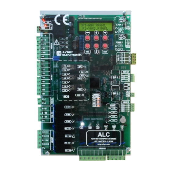
1.5) ELECTRONIC BOARDS IN THE SYSTEM The electronic boards used in ALC system and their descriptions are listed below. ALC: It is the main controller board of ALC system. It contains a microcontroller, an LCD display and a keypad, to manage the system. This board is common in electric and hydraulic lifts. It has 8 programmable inputs and 9 programmable relay outputs on it. -
Page 7: Safety Line
ALPK: This board is used in systems where landing panels are parallel and serves as a call register well as a terminal board for programmable inputs and outputs in controller and PTC. It contains 8 (12) programmable inputs. SPB: This board serves as a pit controller in shaft pit. It communicates via low speed fault tolerant CAN-BUS. - Page 8 Figure 1.1 1.6.2) Safety line structure: Safety line starts to flow from the terminal 110 into the shaft devices. All devices, through which the safety line must passes except lift doors, are to be between 110 and 120. 120 is the starting point of the door safety contacts.
- Page 9 F/7.5.5.02.102 R:1...
-
Page 10: Panel Voltage
1.7) PANEL VOLTAGE Except for the safety line, there is only one power supply in the system which is 24V dc. It is the power source in the controller to supply all electronic boards, signals and detectors. The current rating (power) of the supply must be selected by taking into consideration the current consumption of the panels. -
Page 11: Distance Based Operation
1.11.3) ABSOLUTE ENCODER The best way to get car position information is to use an absolute encoder. An absolute encoder always gives the exact car position information to the controller. It does not need resetting after start-up. An absolute encoder in ALC system is connected via CAN bus. It gives information about car position in mm accuracy. -
Page 12: Priority Function
When hand terminal is active then the keypad on the mainboard becomes inactive. 1.19) DATA TRANSFER ALC series controller supports computer connection via USB or Ethernet by means of Aybeynet software. By using Aybeynet a computer can be connected directly, via a local network (LAN) or via the Internet. -
Page 13: Maintenance Control
1.19.1) USB In order to connect any PC to a lift controller with Aybeynet via USB it is necessary to have a USN add-on board plugged onto the ALC mainboard. So, the controller can be monitored by a PC in the machine room to adjust the parameters and timers or to detect an error. -
Page 14: Chapter 2 - Lcd Screen And Keypad
CHAPTER 2 - LCD SCREEN AND KEYPAD ALC Series have an LCD screen with two lines and sixteen characters per line and a keypad with six buttons. Buttons are located as below: LEFT RIGHT DOWN Figure 2.1 Keypad layout There are arrows in four directions as UP, DOWN, LEFT and RIGHT on the glass of the ALC mainboard. -
Page 15: Startup Screens
After setting the parameter, if you press ENT the new value on the screen is saved. However, if you press ESC, changes are cancelled. In both cases, you return to the previous screen and will see value of the parameter. Here we press ENT and see the following screen. - Page 16 The meaning of the characters on the main screen is explained in the following screens. Please note that the background of the explained positions is in grey and characters are in red. a) The first character gives information about the safety line. The characters and their corresponding safety line status are as follows: terminal character When G is displayed here then the safety line is closed and the lift can move.
- Page 17 01=INS STOP 1 ..g) The positions 9 and 10 show the status of the doors. If there is only one car door then there are two arrows in these positions. When the arrows point toward each other it means the doors are closing or closed otherwise opening or open.
- Page 18 The speed words at these positions and their meanings are shown below. STOP Lift is at rest START Lift is executing a start command but motion has not started yet. LEVEL Lift is relevelling SLOW Lift is in slow motion FAST Lift is in fast motion.
-
Page 19: Button Functions In Main Screen
2.3) BUTTON FUNCTIONS IN MAIN SCREEN The functions of the buttons when pressed while main screen is being displayed are as follows: 2.3.1) Pressing ENT Button -> MAIN MENU When ENT button is pressed then the menu system is activated. Main menu appears as below: >M2-PARAMETERS M3-ERROR LOG... - Page 20 When you do not press any button then the system will return to the main screen after a certain number of seconds. But if you press ENT button here then you will enter into info menu. 12/08/2017 13:04 SERIAL NO 2- 1314 1- DATE TIME...
-
Page 21: Test Menu
As you can see there are certain numbers and ‘*’ signs on this screen. When an input is in active then it will have a ‘*’ on the right side and the inactive ones will be blank. In order to see the states of more inputs, press DOWN button. -
Page 22: User Definable Menu
The functions of the keys in this utility are as follows: LEFT: Pressing LEFT button enables (‘+’) or disables (‘x’) the doors. When the doors are disabled then the lift will continue to work normally, however, the doors will not be opened at floor arrival and no door open command will be responded. -
Page 23: Chapter 3 - Inputs
Figure 3.1 Due to its flexible structure, the input terminals of ALC Series control system are distributed to a number of boards. The places of these terminals are listed below. INPUT NO... - Page 24 INPUT ACTIVE INPUT CODE EXPLANATION DEFINITION STATE Car Top Inspection Switch USER Recall Operation Switch USER Pit Inspection Switch USER High Speed Limit at bottom USER High Speed Limit at top USER Car Inspection Motion Button Down USER Car Inspection Motion Button Up USER Recall Motion Button Down USER...
- Page 25 INPUT ACTIVE INPUT CODE EXPLANATION DEFINITION STATE Current Level Detection (for electric lifts) This input function is used to detect the current level in test phase of the rescue operation. The input terminal of this function is driven by the inverter and any ON state means that the current level is above the set level.
- Page 26 INPUT ACTIVE INPUT CODE EXPLANATION DEFINITION STATE RUN feedback RUN input function is used as a feedback from the motor driver. The system waits for a period of time defined in [C21]- WAIT FOR MOTION timer right after sending motion command.
- Page 27 INPUT ACTIVE INPUT CODE EXPLANATION DEFINITION STATE Disable Switch When this switch is active, any lift motion is inhibited. USER However, relevelling will be carried out when needed. Floor counter switch when the floor selector has been USER Info selected as BI-STABLE. (A05=1). Door Selection Switch for Door 1 This input function can be used when [B18]-TWO DOORS SELECTION = 1 (TERMINAL INPUT).
- Page 28 ACTIVE INPUT INPUT CODE EXPLANATION DEFINITION STATE VIP input 2 When an active signal is present at this input then the USER lift moves to the floor specified in parameter [B34] SECOND VIP FLOOR VIP input 3 When an active signal is present at this input then the USER lift moves to the floor specified in parameter [B35] THIRD VIP FLOOR...
- Page 29 INPUT ACTIVE INPUT CODE EXPLANATION DEFINITION STATE Free input 3. When activated output 108 will be ON. USER Clear Car Calls When this input has been activated all car calls will be USER cleared. Clear Hall Calls When this input has been activated all hall calls will be USER cleared.
- Page 30 INPUT ACTIVE INPUT CODE EXPLANATION DEFINITION STATE MDK Checking It checks if KDK contactors are working synchronously. USER Active state means a faulty operation and error 4 is evoked. Overload Reverse This input is the reverse of Overload Contact (16). USER Overload will be active when [814=1].
-
Page 31: Monitoring Of The States Of The Inputs
INPUT ACTIVE INPUT CODE EXPLANATION DEFINITION STATE Safety Circuit Terminals STANDARD Safety Circuit Terminals STANDARD Safety Circuit Terminals STANDARD Safety Circuit Terminals STANDARD Safety Circuit Terminals STANDARD Safety Circuit Terminals STANDARD Safety Circuit Terminals STANDARD Safety Circuit Monitoring for SDB Board STANDARD Door Zone determining switch 1 STANDARD... -
Page 32: Setting Of Input Terminals
However, a signal at the terminal which makes its sign “+” does not always mean that this function is active. Similarly, also a star sign “*” displayed at the end of the first line does not always mean that this function is active. Some input functions are inactive when there is a signal at the terminal and become active when the signal is removed. -
Page 33: Setting All Inputs By A Command
The message on this screen means that the function code 870 has been defined previously at the terminal I9. Therefore, you cannot assign it once more to any other terminal. All of the input functions are listed and explained in section 3.2. 3.6) SETTING ALL INPUTS BY A COMMAND All programmable input terminals can be defined one by one. -
Page 34: Location And Specification Of Outputs
Figure 4.1 4.2) LOCATION AND SPECIFICATION OF OUTPUTS ALC Series has 33 programmable outputs. The positions, types and electrical specifications of the outputs are given below. CODE PLACE CONTACT V/I CONTACT TYPE EXPLANATION 220V/10A Normally Open Freely programmable in all lift types. - Page 35 CODE OUTPUT FUNCTION EXPLANATION HYDRAULIC MOTOR Hydraulic motor output DELTA CONTACTOR Hydraulic delta contactor output STAR CONTACTOR Hydraulic star contactor output NORMAL OPERATION System is in normal mode FAULT OCCURANCE There is an error INSPECTION System is in inspection SLOW MOTION The car is moving at slow speed NO SLOW MOTION The car is not moving at slow speed...
- Page 36 CODE OUTPUT FUNCTION EXPLANATION GONG Gong Signal is ON LEVELLING Levelling FIRE - NO ENTRY Fire signal is active. (FR1or FR2) DOOR BRIDGING Door pre-opening MOTOR CONTACTOR 2 Motor contactor output 2 for Fuji closed loop reserve Not used 120 ON 120 Terminal is ON 120 OFF 120 Terminal is OFF.
- Page 37 CODE OUTPUT FUNCTION EXPLANATION Output for speed governor coil used for UCM in geared SPEED GOVERNOR COIL systems. There is one or more hall calls registered. HALL CALL SIGNAL It is only then active when WM2 input is used. DOWN IN FIRE Lift is moving in downwards direction in case of fire UP IN FIRE Lift is moving in upwards direction in case of fire...
-
Page 38: Defining Outputs
CODE OUTPUT FUNCTION EXPLANATION MAXIMUM DIRECTION Maximum direction counter exceeded the limit defined in CHANGE PB-MAX.DIRECTION CHANGE parameter. This output is on while the controller is receiving messages from the car controller. If the communication is off (error CAR COMMUNICATION OK 18) then this output becomes passive for three seconds and then becomes active again after three second. -
Page 39: Chapter 5- Parameters
output function will be assigned to this output terminal. In any instant you can leave the screen by pressing ENT button without changing any record. CHAPTER 5- PARAMETERS All information about lift and control system settings and timings are stored in system parameters. -
Page 40: P1-Main Parameters
5.1) P1-MAIN PARAMETERS The lift must be stationary (in REST mode) mode to carry on any modification on main parameters. [A01] NUMBER OF STOPS This parameter stores the number of stops of the lift. 2…64 [A02] COMMAND SYSTEM Simple Push Button Car and hall calls are processed together. - Page 41 [A05] FLOOR SELECTOR Counter Mono-stable Switch Monostable magnet switches are used for car position detection. Counter Bi-Stable Switch Bi-stable magnet switches are used for car position detection. Incremental Encoder Incremental encoder is used for car position detection. See section 10.1 for detailed installation instructions. Absolute Encoder Absolute encoder is used for car position detection.
- Page 42 [A10] TARGET DISTANCE Floor Number Floor numbers are taken as reference to calculate the distance to the target. Therefore, there is only one position reference for each floor. Distance Encoder pulses are used as reference to calculate the distance to the target. Therefore, there are lots of position references for a floor in mm accuracy.
- Page 43 [A14] MISSING DOWN (GROUP LIFT) This parameter is used only for group operations. If there are one or more floors of the other lifts in the group below the base floor of 0…5 this lift then the number of missing floors downwards must be defined in this parameter.
- Page 44 [A17] RELEVELING DETECTOR MKU and MKD MKU and MKD switches are used to control relevelling process. Relevelling will be initiated by using the information coming from MKU and MKD switches. Select this option if the encoder on motor is used as floor selector device. ENCODER Encoder pulses are used to control relevelling process.
- Page 45 [A24] PAWL DEVICE NOT USED PAWL DEVICE is not used PAWL NS 40/50 PAWL DEVICE model PAWL NS 40/50 is used. PAWL NS 70/100 PAWL DEVICE model PAWL NS 70/100 is used [A25] MECHANICAL CAM NOT USED PRESENT Mechanic Cam is used for swing landing doors. 5.2) P2-AUXILIARY PARAMETERS [B01] AFTER LOCK FAULT Continue...
- Page 46 [B03] PARK DEFINITION No Park Floor No park floor is defined. Park Floor with closed doors The car will go to the parking floor set in parameter [B04] when no calls have been received in a specified time period [C25] after the car light goes off. The car will wait at parking floor [B04] with closed doors.
- Page 47 [B09] WAIT DOOR OPEN Wait Closed Car waits with closed doors at floor level. Wait Open Car waits with open doors at floor level. Warning: This option is not in conformity with EN81-20/50. [B10] REMOTE REPORTING Not Activated PC COMMUNICATION GSM SMS After an error, system sends a SMS to the defined phone number.
- Page 48 [B15] RECALL SPEED SELECTION REV-JOG OFF Output No:33 will not be active in recall motion. Output No:105 can be used to activate an extra speed. REV-JOG ON Output No:33 will be active in recall motion mode. Recall speed is the same as the inspection speed. [B16] BUTTON FAULT CONTROL NOT ACTIVATED This function is not active.
- Page 49 [B20] INSPECTION SPEED Fast (Hydraulic) This option can be set only in hydraulic lifts. The speed in inspection mode is selected as the fast speed. Slow The speed in inspection mode is selected as the slow speed. Only Direction When there is a motion command in inspection mode then only the output related to the direction command is set, neither slow nor high speed is activated.
- Page 50 [B24] PHASE CONTROL This parameter determines how the state of 3-phase line inputs must be processed. PHASE CONTROL OFF No control for 3-phase line inputs are carried out. On-board L1/R, L2/S and L3/T inputs on ALC mainboard are used to process 3-phase control. FKI Input An external phase detector connected to the input terminal assigned to FKI input function is used to process 3-phase control.
- Page 51 [B28] RESCUE SPEED This parameter defines the states of speed outputs for motor driver in rescue mode when a motion command is executed. Fast + Inspection Both fast and inspection speed outputs are active. Fast Only fast speed output is active. Slow Only slow speed output is active.
- Page 52 [B32] GONG SELECTION This parameter defines how the arrival gong is executed. Gong at Stop Gong signal is activated when the lift stops. Gong at Slow Speed Gong signal is activated when the lift starts to slow down. No Car Gong There is no arrival gong. [B33] 1 VIP FLOOR When the input terminal assigned to VP1 input function is activated then the lift...
- Page 53 [B38] CAR DISPLAY OUTPUT This parameter defines how the digital outputs of SDE board on car controller SCB board are driven. 7 Segment Display Digital outputs are 7 segment display data. Grey Code Output Digital display outputs on SCB board give Grey Code output where the digit G represents G0, digit F represents G1, digit E represents G2 and digit D represents G3.
- Page 54 [B44] MK DELAY This parameter defines the delay in stopping after the stop magnet switch has been read by the system in normal operation. One unit in this parameter corresponds to a 0…90 time delay of 30 msec. Parameter unit is 30 msec. When this parameter is set as 0 then this function is disabled.
- Page 55 [B49] RELEVELING MOTOR This parameter is used only for hydraulic lifts to define the presence of an extra levelling motor. No There is no levelling motor. Yes There is a levelling motor. It will be activated only in case of level motion. [B50] CNT CHECKING This parameter defines the way contactors are checked.
- Page 56 [B54] INSTALATION MODE This parameter has been implemented to facilitate the first installation of the system. System must be inspection mode due to inspection box or RECALL switches to activate this function. Some of the inputs are inhibited as long as install mode is active. When the controller returns to the normal mode or system is restarted then this parameter is returns to passive (B54=0) automatically and installation mode is cleared.
- Page 57 [B58] AMI-100 DEVICE This parameter is used for AMI-100 device to implement EN81-21 requirements. Not Used AMI-100 device is not used. Present AMI-100 device is employed in the system. [B59] BRIDGING BLOCK This parameter determines if the system will be blocked after the occurrence of the error 45. Can Be Blocked The system will be blocked after error 45 (bridging error).
-
Page 58: P3-Timer Parameters
[B63] DOORS IN FIRE This parameter determines the door status at fire while the car rests at fire exit floor if EN81-73 is selected [A46=0]. Doors wait open at fire exit. Doors wait closed at fire exit. [B64] EMERGENCY PHONE BUTTON This parameter determines which button in car operating panel will initiate a call by emergency phone. - Page 59 [C05] K20 PERIOD When K20 input function is activated then door-1 will open. Then it will wait for the 10…200 time period specified in this parameter before closing back. [C06] PHOTOCELL PERIOD-1 When FOT input function is activated then door-1 will open. Then it will wait for the 10…200 time period specified in this parameter before closing back.
- Page 60 [C16] SLOW SPEED MAXIMUM PERIOD This parameter stores the maximum travel time allowed to pass when the car is in slow 50…1000 speed. When this time is passed, error (6) is generated and the system is blocked. [C17] ARCH TRAVEL Designed for the system where the distance between two stops is very short.
- Page 61 [C26] I-Valve START SMA-OFF The turning OFF period at start of SMA Signal for Bucher i-Valve hydraulic unit. 1,2…70 Controller checks RDY input. RDY input has to OFF within this time period. Otherwise error 75 is generated. [C27] I-Valve STOP SMA-ON The turning on period at stop of SMA Signal for Bucher i-Valve hydraulic unit.
- Page 62 [C36] PHOTOCELL PERIOD 2 When FT2 input function is activated continuously for the time period defined in this 10…200 parameter then door-2 switches to slow close-2 mode and activates slow closing-2 for the door-2 provided that other than 0 is selected in parameter B51. [C37] PHOTOCELL BYPASS PERIOD 2 When FT2 input function is activated continuously for the time period defined in this 50…3000...
- Page 63 [C46] PAWL MOTION UP This period specifies the period of special pawl up motion when the lift starts for any 0…50 direction. [C47] PAWL LOCK WAIT 0…50 The maximum waiting period after energizing the PAWL device until SKN is read ON. [C48] PAWL PRESSURE WAIT The maximum period for KNB to be read as ON after starting special PAWL motion in 0…50...
-
Page 64: Chapter 6 - Floor Parameters
CHAPTER 6 - FLOOR PARAMETERS In this section, the parameter related to the floor numbers will be explained. We call these parameters “Floor Parameters”. The path for Floor parameters is as follows: main menu [press ENT] -> M2-PARAMETERS -> P4-FLOOR PARAM. >K1-SET DISPLAYS K2-SET DOOR 1 Menu M24 consists of the following sections:... -
Page 65: K2-Set Door Aand K3-Set Door B
be displayed in car and landing panels. However, the hardware you are using to drive and display these characters limits the characters you actually see on the displays. For example, if you have 7-segment digital displays on your panels then you can see the characters of all digits from 0 to 9 and other characters like -, A, b, C, d, E, F, H, I, J, L, n, P, r, U, y. -
Page 66: K4-Car Calls
6.3) K4-CAR CALLS You can set cabin call permissions for any floor by using this section. If you switch off cabin call of any floor then any call coming from car operating panel will be discarded. When you enter this section by pressing (ENT) button in menu M24, you will see the following screen. -
Page 67: K6-Encoder Pulse Of Floors
The parameters used in this screen are as follows OFF Hall calls for this floor are not allowed ON Hall calls for this floor are always allowed. PE1 If the clock time is within the time interval PERIOD1 that is specified in section K8, then the hall calls are allowed, otherwise not allowed. -
Page 68: K7-General Pulse
6.6) K7-GENERAL PULSE This parameter is used only if [A05] is 3 (incremental encoder) or 4 (absolute encoder). The parameters given in this section correspond to the distances that are used for all floors. When you change any pulse number, then the distance for the related path is changed in all floors. All of the data given in this section are the distances in encoder pulses for the floor level specified in the previous section. -
Page 69: Chapter 7 - System Settings
CHAPTER 7 - SYSTEM SETTINGS 7.1) SETTING DATE & TIME System time and date can be set in this section. You can enter this service routine through the following path main menu [press ENT] -> M2-PARAMETERS -> P8-DATE & TIME The time and date of the system can be set in this section. -
Page 70: Chapter 8 - Lift Functions
PASSWORD ?002345 NEW PASS ?003200 ?000000 OFF Confirm New Pass 01.FLOOR KAPI A ENTER-SAVE ?000000 OFF 01.FLOOR KAPI A If you enter the password correctly, system permits you to change system password to a number ?000000 OFF between 0 and 32000. When you press ENT button the new password will be saved. However, you ?000000 OFF 01.FLOOR KAPI A can cancel changes by pressing ESC button. -
Page 71: Priority Function
f) When the master is switched off or cannot travel for any purpose then the lift with the lowest group number among the remaining lifts will be assigned as the new master and group operation will be carried out without interruption. g) When a lift is not in normal mode or is blocked then it will be excluded from the group. -
Page 72: Access Control System
The lift does not accept any landing calls throughout the priority service time. Only car buttons can be used to move the lift during this period. The priority operation will be terminated when the access control reader inside the car is activated by the priority key for the second time. - Page 73 Table 8.1 Allowance for ID keys All Floors To allow all floors, choose 1 with UP and DOWN buttons and press ENT. Allowed (Floors = FFFFFFFF) No Floors To restrict all floors, choose 2 UP and DOWN buttons and press ENT. Allowed (Floors = 00000000) 0 –...
- Page 74 8.3.3) ACTIVE FORMAT In this section you can select the default format which will be active when you enter the “ADD NEW ID” operation. 8.3.4) ADD NEW ID To add a new ID, select Y2-ADD NEW ID line with UP and DOWN buttons and press (ENT) button. On the new screen, system will wait for you to show a key or card to any station to read.
-
Page 75: Maintenance Control
All Floors In order to allow all floors, select '1' as operation code by UP and DOWN buttons Allowed and press ENT key. No Floors In order to restrict all floors, select '2' as operation code by UP and DOWN Allowed buttons and press ENT key. -
Page 76: Chapter 9 - Utilities
CHAPTER 9 - UTILITIES 9.1) FACTORY DEFAULTS When you are first starting with the controller or you want to clear all of the current parameters to reorganize them, you can set factory defaults. In this operation all parameters are first cleared and then set according to the lift type you have specified. -
Page 77: Display Utilities
OP.CODE ?000000 You should enter 536 to run backup routine. OP.CODE ?000536 When you enter to confirm this code then you will be asked again to confirm executing backup operation. TEST VALUES SAVE (↑)-CONFIRM Press UP button to save a backup of all parameters. 9.2.2) RESTORING BACKUP PARAMETERS To restore the parameter set from the backup, you should first go from the main menu through the following path:... -
Page 78: R5-Reset Pulses
number. If you specify which floor is the entrance floor of the building, then this utility sets the digital display of the entrance floor (base floor) as 0. All floors above this floor are numbered starting 1 and incremented by 1 at every floor; all floors below 0 (base floor) are numbered starting -1 and decremented by 1 at every floor. - Page 79 c) Encoder simulation outputs of the inverter: The encoder input terminals of ALC are connected to the simulation output of the inverter. The inverter outputs the encoder signal received from the motor encoder to the controller. However, in this situation, the controller cannot detect any car position change when there is no motion while the car rests at the floor.
-
Page 80: Absolute Encoder
To start the operation, press UP button when you see the following screen. SHAFT LEARNING (↑)-START When the learning operation starts you will be asked certain questions. The first one is the length of the slow down path. All lengths in encoder operation are in mm. You can change the ?000000 OFF data with UP and DOWN buttons and confirm by pressing ENT button. - Page 81 absolute encoder is used. The encoder always sends the controller the exact car position regardless of any power failure. 10.2.1) ABSOLUTE ENCODER SETUP In this section you can execute the service routine for encoder auto learning process. The controller learns the position of the floors and shaft limits through executing this process. At the end of the learning process the floor positions will be saved and used in further travels.
- Page 82 Figure 10.3 : Absolute encoder magnet map (LIMAX 2M) F/7.5.5.02102 R:2...
- Page 83 10.2.2) SHAFT LEARNING FOR ABSOLUTE ENCODER After completing installation of the encoder and shaft switches, go to encoder setup service routine through the following path: main menu [press ENT] -> M2-PARAMETERS -> P9-UTILITIES -> RA-ENCODER SETUP main menu [press ENT] -> M8-ENCODER SERVICE -> E1-LEARN SHAFT >E1-LEARN SHAFT In order to start learning the lift must be switched on to the E2-ADJUST IN CA...
- Page 84 If the car is at floor level confirm it or move it to catch the 1000 3892 floor level and confirm then as explained above. FLR:?1 8423 6021 Continue the operation in this way till to the last floor. After Operation complete confirming the level of the last floor the operation will be ?000000 OFF...
- Page 85 When the operation starts the controller will open the doors completely and cancel landing calls where car calls will remain active. In this procedure first two call buttons and door close button on COP are going to be used as command panel. The door is always open during level adjustment motion as in re-levelling.
-
Page 86: Distance Based Operation
10.3) DISTANCE BASED OPERATION 10.3.1) OPERATION: When the parameter A10 is 1 then the controller switches to distance-based operation system. In distance-based operation the distance to the target floor in mm is used in motion rather than floor number as is the case where A10=0. Distance based operation has significant advantages in high speed lifts. -
Page 87: Chapter 11 - Error Log And Error Codes
CHAPTER 11 - ERROR LOG AND ERROR CODES In ALC Series Control Systems, all determined errors are reported at runtime on main screen and stored in permanent memory. Error storing capacity of system is limited to 250. If an error occurs when there are 250 errors stored in memory, then oldest error is cleared and the new one is stored. -
Page 88: Alc Series Error Codes
11.1) ALC SERIES ERROR CODES CODE ERROR EXPLANATION Stop circuit-120 (Speed regulator, parachute contact, stop buttons…) Stop Circuit Open is open. 125-135 is Open Door Contact circuit 125-130 is open during motion. 140 is Open Door Lock circuit-140 is open during motion. - Page 89 CODE ERROR EXPLANATION System cannot communicate with hall units in serial mode. Check serial communication states of the main board and the hall units. If BE or LE leds on CAN drivers are ON then there is something wrong either Landing Control in electrical wiring of CAN units or in values of the termination Communication...
- Page 90 CODE ERROR EXPLANATION If ML2 switch becomes passive [ML2=0] while the car is staying at floor level this error is created. If the doors are open then it is an UCM error ML2 Open at Floor and the system is blocked. Check the magnet and switch locations of ML1 and ML2.
- Page 91 CODE ERROR EXPLANATION When the fire inputs FR1 and FR2 return to normal positions, [FR1=1] and [FR2=1], after a fire state then the system will not return to normal, if the parameter B46 was set to 4 [B46=4]. The system will be Fire Reset blocked in this case.
- Page 92 CODE ERROR EXPLANATION This error is reported in hydraulic lifts during valve test if the down Down Valve Fault valve failed and the system is blocked. The electrical connections of the valve as well as the mechanical functions must be checked. When the motion has been started and coil on the overspeed governor Governor Contact has already been energized, if SGO input signal is still high [SGO=1],...
- Page 93 CODE ERROR EXPLANATION If ALSK or ALPK board is not present or not connected to the car CAN- bus or there is a communication fault in this bus, then this error is ALSK Not Present reported. Check terminal board, CAN bus wiring and 24V power supply (100-1000).
-
Page 94: Chapter 12 - Ucm Services
CODE ERROR EXPLANATION Pawl Compressed Car is not at floor level but KNB=0. An upwards motion has been started due to the low pressure in piston Pawl Low Pressure but LRP input does not become 0 in allowed time. In Pawl landing motion the car has exceeded floor level but KNB did not Pawl Not Pressed become 1. -
Page 95: Ucm In Electric Lifts With Asynchronous Motor
12.1.3) UCM Detection (Unintended Car Motion) a. While the Car is Resting at Floor Level Whatever the drive system is, if the car moves outside to the door zone while staying at the floor level and the doors are open then this will be considered by the controller as an UCM error (ML1 or ML2 is 0). -
Page 96: Ucm In Electric Lifts With Synchronous Motor (Gearless Machine)
pulled back. So, the speed governor can rotate freely while the car is moving. Any attempt to move the car while the pin is not pulled back causes in activation of safety gears. When the coil is energized then the pin inserted into the wheel of the governor will be pulled back. -
Page 97: Ucm In Hydraulic Lifts
When the controller starts motion then the brakes are opened. This makes these contacts off (0). In this case, if any one or both of the BR1 and BR2 inputs keep to be high (1) after 3 seconds, then the controller switches the system to BLOCK mode and “Error No:65 Brake Not Opened” will be displayed on the screen. -
Page 98: Manual Ucm Test
time set in menu U3. To set the starting time of the test use menu U3 shown in the following path. main menu [ENT] -> M7-UCM SERVİS -> U3-TEST TIME >U3)TEST TIME U4)TEST START 12.4.1.2 Test of Down Safety Valve ?000000 OFF Manual test for down motion valve and the down safety valve is described below. -
Page 99: Shaft Limit Test
mode and the cabin light (Busy signal is off) must be turned off to ensure that the lift is not in use. Test operation cannot be performed in inspection mode. 12.5.2 Test Procedure “TEST SPEED: SLOW” is displayed on the screen. You can switch between HIGH and SLOW speeds by pressing RIGHT (>) and LEFT (<) buttons. -
Page 100: Chapter 13 - Electronic Rescue System
This utility can be executed through: main menu [ENT] -> M7-UCM SERVİS -> U8-SHAFT LIMIT TEST When executed, the lift moves up (at top floor) or down (at bottom floor) in slow speed in order to exceed shaft limits. The travel is terminated by opening the limit stop switches. So, the emergence of the stop error indicates that the limit switches are working properly. - Page 101 Figure 13.2: N Type Rescue System Connection Diagram 13.1.3 C Type Rescue System (For Traction Lift) C-type rescue system is used only for hydraulic lifts. In this system only UPS is used as energy source for the lift. It is shown in Figure-13.3. Figure 13.3: C Type Rescue System Connection Diagram F/7.5.5.02102 R:2...
-
Page 102: Definitions And Parameters Used With Rescue Application
13.2) Definitions and Parameters used with Rescue Application 13.2.1 Input Definitions: This input is used to check KUPS contactor. ERS (32): This input used only if there is an external main phase detector (parameter B24 = 2). FKI (49): The system enters into rescue mode if this input goes off, 0. It is used to determine the rescue motion direction. - Page 103 KUPS is controlled via the ERS input (32), which pulls and energizes the power circuit. When the ERS input active, the controller starts to rescue. The direction of the rescue motion can be determined either by the controller or by the motor driver Direction Determined by the Motor Driver If the motor driver determines the rescue motion direction then ERU (26) input is used to transmit this information to the controller.
-
Page 104: Chapter 14 - En81-21 Low Pit/Low Headroom Applications
CHAPTER 14 – EN81-21 LOW PIT/LOW HEADROOM APPLICATIONS EN81-21 standard sets the basic rules to design lifts which do not satisfy shaft requirements of EN81-20/50. It is obvious that the risk analysis is based on the mechanical design of the lift. However, the controller is involved into the process to detect dangerous situations to inhibit or prevent motion. -
Page 105: Checking Of Manual Opening Of Shaft Doors With Triangular Key
AMI-100 Related Parameters are as follows: [B58] AMI-100 DEVICE No AMI-100 AMI-100 device operation is enabled. Output: O 113 Amı-100 device coil output (for EN81-21) Input: 80-ARN ARN This input is active when AMI-device has been retracted. Input: 81-ARD ARD This input is active when AMI-device has not been extended. Error No ARN=0 when AMI coil is activated or ARN=1 when ARN Contact Error... -
Page 106: Chapter 15- Variables And Language
Figure 14.2 Landing Doors with Normally Closed Contacts 14.2.2 Landing Doors with Bi-Stable Contacts If a system has bi-stable contacts for landing doors then there is no need to use KDK contactors. Refer to the manufacturer’s data sheet of the landing door contacts. CHAPTER 15- VARIABLES AND LANGUAGE On main menu you see M1-VARIABLES at first line. - Page 107 This is a shortcut to menu [B11] which is explained above. You can change the language from this menu. When this manual was prepared, supported languages were Turkish, English, German, French, Russian, Spanish and Greek. New languages will be supported in the near future. The last item in main menu is M4-SERVICES.
- Page 108 Sanayi Mah. Hızır Reis Cad. No:26 34906 Pendik – İstanbul / Turkey Tel: (90) (216) 394 50 55 (pbx) Faks: (90) (216) 394 50 58 e-mail: support@aybey.com www.aybey.com...
Need help?
Do you have a question about the ALC Series and is the answer not in the manual?
Questions and answers