Advertisement
Quick Links
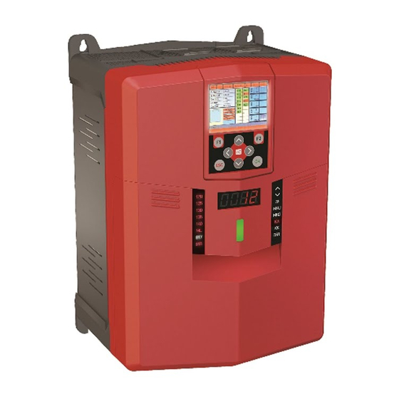
Integrated Lift Control System
for Electric Package of Gearless Lift Machines
Document Name
Document Code
Document Version
Software Version
AE-MAESTRO
INSTALLATION MANUAL
: AE-MAESTRO Lift Controller Installation Manual
for Electric Package of Gearless Lift Machines
: AEM-INSEN-GL
: 1.08d
: 2.20u (Lift Control) / 2.20g (Motor Driver)
www.aybey.com
Advertisement

Related Manuals for Aybey Elektronik AE-MAESTRO


Summary of Contents for Aybey Elektronik AE-MAESTRO
- Page 1 AE-MAESTRO Integrated Lift Control System INSTALLATION MANUAL for Electric Package of Gearless Lift Machines Document Name : AE-MAESTRO Lift Controller Installation Manual for Electric Package of Gearless Lift Machines Document Code : AEM-INSEN-GL Document Version : 1.08d Software Version : 2.20u (Lift Control) / 2.20g (Motor Driver)
- Page 2 This document is written to guide installation of the lift controller for pre-wired system. It guides the installation of electric system of the lift. This document should be used in together with AE-MAESTRO Integrated Lift Controller and Hand Terminal user manuals.
- Page 3 THE ELECTRICAL COMPONENTS IN SHAFT 1. Lift Control Panel 2. Recall Command Box 3. Inspection Command Box 4. Cartop Emergency Lighting 5. Cartop Box 6. Audible and Flashing Device 7. Pit Control Unit 8. Pit Command Box 9. Pit Inspection Reset Switch 10.
- Page 4 THE COMPONENTS USED IN SHAFT AND MACHINE ROOM Prewired Inspection Box KDM Pit Control Box Pit Stop, Socket and Inspection and Recall Alarm Box Command Box In cartop, controller and pit to move the car Controls car circuit Controls pit circuit Connected to Controller Stop Button Audible and Visual...
-
Page 5: Connecting Motor Power
CONNECTING LINE SUPPLY Connect power line cables to the terminals L1/R, L2/S, L3/T and N. CONNECTING MOTOR POWER 1. Connect motor power inputs to U, V, W terminals in controller box. 2. Use the given shielded motor cable for this. 3. - Page 6 CONNECTING BRAKE, THERMISTOR AND MACHINE SIDE STOP 1. Motor brakes, thermistor and stop are placed in XK- BRK2 terminal group in controller box. 2. Connect motor thermistor to T1 and T2 terminals in controller box. 3. If there is no thermistor in motor then bridge T1 and T2 terminals in controller.
- Page 7 In order to start with autotuning operation safety line must be closed. If safety line has been already bridged on HT-KL board with first installation cables in control panel, then these cables must be removed after termination of the installation process! ...
- Page 8 7. Take other end of 24 wire flex cable and connect its terminals labelled with… XH-HV3 XL-LV2 XH-HV1 XH-HV2 to their corresponding sockets on PWL and PWH boards in cartop inspection box. 8. Take other end of 12 wire flex cable and connect its terminals labelled with XL-LV1 to its corresponding socket on PWL board in cartop inspection box.
- Page 9 CONNECTING LANDING PANELS 1. Read the manual of landing panels (LOP) in Appendix-3, AP-03. 2. Landing panels are serially connected and must have a unique floor number id to communicate. 3. All LOPs are delivered as their floor numbers already saved. 4.
- Page 10 CONNECTING SHAFT PIT (Only for EN81-20 Standard) Connect XK-KDM-SF1 and XK-KDM-PWR sockets to the controller to implement shaft pit. Connect SPT board, which is in shaft pit box KDM, to the socket of the LOP in ground floor. ...
- Page 11 ENCODER CONNECTIONS FOR GEARLESS MACHINES 1. Open the front cover of the device. ICA board should be placed on the right side. 2. Check the supply voltage information of the encoder. 3. Read the product code written on the encoder and check if it matches to one of encoders given below.
- Page 12 The software of the device can be updated by using hand terminal. Program file is transferred from an SD card. Read AE-MAESTRO Hand Terminal manual before going further. You will need it to monitor the lift, edit parameters and performing operations.
- Page 13 Press ENT button to go to the menu. In this screen you can move by using cursor keys (arrows). In order to enter into an application or sub-menu come to the related icon by using cursor keys on the screen and press ENT when its icon is highlighted.
-
Page 14: Loading And Saving Parameters
LOADING AND SAVING PARAMETERS The parameter set of the device can be saved into the SD card and reloaded from it again. So, the parameters can be back-up, transferred to another device or restored from the file in SD card. ... -
Page 15: Initial Parameter Setup
INITIAL PARAMETER SETUP AE-MAESTRO has an interactive installation menu which can be used to set most of the general parameters. Using this menu facilitates setting up the system. You will be asked to set requested parameters one by one depending on the previous selections. -
Page 16: Auto Tuning
The last screen in setup menu is M18 Tuning Mode. If you confirm this parameter, setup operation will be terminated and you will be directed to the tuning operation. If you want, you can leave the setup program now and execute tuning later. - Page 17 TUNING IN OPERATION Turn on INSPECTION switch on recall command box to INSP position. The system must stay in inspection mode and safety line must be closed along the operation to execute tuning process. To start tuning operation, select R04-TUNING under SERVICES icon.
- Page 18 IN OPERATION In stationary tuning… Since there will be no rotation, brakes must be held closed along the operation. However, if the brakes are not adjusted well to hold the machine fixed then the motor may rotate. In this case tuning operation fails.
- Page 19 DIRECTION TEST Give a motion command by pressing RUN and UP or DOWN buttons in recall command box. Observe the motion of the car. If the car travel direction is opposite to the command direction given, then reverse the value of the parameter M19 MOTOR DIRECTION in MOTOR PARAMETERS.
- Page 20 CAR ILLUMINATION CONTROL There is a detection system for car illumination control inside car operating panel. It inhibits the motion of the car if the light inside the cabin goes off, while the car light is on (busy signal on). ...
- Page 21 CAR LIMIT SWITCH Mount mechanical limit switch with roller by using supplied metal bracket onto the cartop. Connect its cable to X-KLSK socket to PWH board in inspection box. Move the car to downwards with inspection or recall command to the position where the car is just below the shaft limit.
- Page 22 This facility can be used later for troubleshooting by enabling or disabling some peripherals. ANTI-ROLLBACK and PRE-TORQUE ADJUSTMENTS AE-MAESTRO offers mainly two technics to prevent anti- rollback in starting phase. One is ANTI-ROLLBACK application. Second one is PRE-TORQUE with load sensor feedback.
Need help?
Do you have a question about the AE-MAESTRO and is the answer not in the manual?
Questions and answers