Table of Contents
Advertisement
Quick Links
www.weiderfitness.com
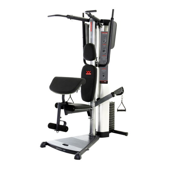
Model No. WESY4998.0
Serial No.
Write the serial number in the
space above for future reference.
Serial Number Decal (under seat)
QUESTIONS?
As a manufacturer, we are com-
mitted to providing complete cus-
tomer satisfaction. If you have
questions, or if parts are missing,
DO NOT CONTACT THE STORE;
please contact Customer Care.
IMPORTANT: You must note the
product model number and
serial number (see the drawing
above) before contacting us:
1-877-992-5999
CALL TOLL-FREE:
Mon.–Fri. 6 a.m.–6 p.m. MT
Sat. 8 a.m.–4 p.m. MT
ON THE WEB:
www.weiderservice.com
CAUTION
Read all precautions and instruc-
tions in this manual before using
this equipment. Save this manual
for future reference.
All manuals and user guides at all-guides.com
USERʼS MANUAL
Advertisement
Table of Contents

Related Manuals for WEIDER CLUB 8980 W


Summary of Contents for WEIDER CLUB 8980 W
- Page 1 All manuals and user guides at all-guides.com www.weiderfitness.com USERʼS MANUAL Model No. WESY4998.0 Serial No. Write the serial number in the space above for future reference. Serial Number Decal (under seat) QUESTIONS? As a manufacturer, we are com- mitted to providing complete cus- tomer satisfaction.
-
Page 2: Table Of Contents
All manuals and user guides at all-guides.com TABLE OF CONTENTS WARNING DECAL PLACEMENT ............. .2 IMPORTANT PRECAUTIONS . -
Page 3: Important Precautions
All manuals and user guides at all-guides.com IMPORTANT PRECAUTIONS WARNING: To reduce the risk of serious injury, read all important precautions and instructions in this manual and all warnings on the weight system before using the weight system. ICON assumes no responsibility for personal injury or property damage sustained by or through the use of this product. -
Page 4: Before You Begin
Thank you for selecting the versatile WEIDER CLUB™ manual. To help us assist you, note the product model 8980 W weight system. The weight system offers a number and serial number before contacting us. The selection of weight stations designed to develop every model number and the location of the serial number major muscle group of the body. -
Page 5: Part Identification Chart
All manuals and user guides at all-guides.com PART IDENTIFICATION CHART Refer to the drawings below to identify small parts used in assembly. The number in parentheses by each draw- ing is the key number of the part, from the PART LIST in the center of this manual. Note: Some small parts may have been preattached. -
Page 6: Assembly
All manuals and user guides at all-guides.com ASSEMBLY dispose of the packing materials until assembly is Make Assembly Easier completed. Everything in this manual is designed to ensure • For help identifying small parts, use the PART that the weight system can be assembled suc- IDENTIFICATION CHART on page 5. - Page 7 All manuals and user guides at all-guides.com 2. Press the 110mm Round Inner Cap (42) into the Upright (3). Set the Upright (3) on the Base (1). Have a sec- ond person hold the Upright until this step is com- pleted.
- Page 8 All manuals and user guides at all-guides.com 4. Insert the Weight Selector (11) into a Weight (17). Make sure that the side of the Weight Selector with the dimpled holes is facing the indicated slot in the Weight. Make sure that the indicat- ed slot in the Weight is oriented as shown.
- Page 9 All manuals and user guides at all-guides.com 6. Slide three M6 Washers (78) onto three M6 x 140mm Screws (79), and insert the Screws into the Upright (3) through the indicated holes. Orient the VKR Bumper (95) with the wide end on top.
- Page 10 All manuals and user guides at all-guides.com 8. Slide the Top Frame (4) onto the Weight Guides (10). Attach the Top Frame to the Weight Guides with two M8 x 89mm Bolts (64), four M8 Washers (72), two 25mm Spacers (47), and two M8 Locknuts (74).
- Page 11 All manuals and user guides at all-guides.com 11. Attach the Press Arm (8) without the wire to the Upright (3) with four M10 x 25mm Screws (58). Remove the M4 x 5mm Screw (69) and the Swivel Arm (16). Route the Press Arm Cable (30) through the Swivel Arm and the Press Arm (8) as shown.
- Page 12 All manuals and user guides at all-guides.com 14. Wrap the Press Arm Cable (30) over a 3 1/2" Pulley (24) and route the Cable through the Top Cover (15) as shown. Attach the 3 1/2" Pulley (24) and a Cable Trap (28) to the Top Frame (4) with an M10 x 45mm Bolt (65) and an M10 Locknut (73).
- Page 13 All manuals and user guides at all-guides.com 18. Route the Press Arm Cable (30) through the Top Cover (15). Wrap the Press Arm Cable (30) over a 3 1/2" Pulley (24). Attach the Pulley and a Cable Trap (28) to the Top Frame (4) with an M10 x 45mm Bolt (65) and an M10 Locknut (73).
- Page 14 All manuals and user guides at all-guides.com 21. Make sure that the Press Arm Cable (30) is routed under the indicated welded rods. Welded Attach a V-pulley (22) to the Swivel Arm (16) with Rods an M10 x 64mm Button Bolt (75), two M10 Washers (71), two 5mm Spacers (25), and an M10 Locknut (73).
- Page 15 All manuals and user guides at all-guides.com 25. Attach the Bumper (49) to the Leg Lever (7) with an M4 x 16mm Screw (70). Grease Apply grease to an M10 x 71mm Bolt (67). Attach the Leg Lever (7) to the Seat Frame (6) with the Bolt and an M10 Locknut (73).
- Page 16 All manuals and user guides at all-guides.com 28. Attach the Curl Pad (87) and the Curl Pad Base (86) to the Curl Post (85) with two M6 x 25mm Screws (60). 29. Make sure that all parts have been properly tightened before the weight system is used.
-
Page 17: Adjustment
All manuals and user guides at all-guides.com ADJUSTMENT This section explains how to adjust the weight system. See the EXERCISE GUIDELINES on page 21 for important information about how to get the most benefit from your exercise program. Also, refer to the accom- panying exercise guide to see the correct form for several exercises. - Page 18 All manuals and user guides at all-guides.com ADJUSTING THE SEAT FRAME HEIGHT To adjust the height of the Seat Frame (6), or to remove it for exercising with the squat bar, unhook the Seat Frame from the indicated brackets on the Upright (3).
- Page 19 All manuals and user guides at all-guides.com ADJUSTING THE VKR FRAME To adjust the VKR Frame (82), remove the VKR Pin (101) from the Frame and the Upright (3). Move the Frame down to use the Frame to exercise, or up to the stored position.
-
Page 20: Cable Diagram
All manuals and user guides at all-guides.com CABLE DIAGRAM The cable diagram shows the proper routing of the Press Arm Cable (30). Use the diagram to Press Arm Cable (30) make sure that the Cable has been assembled correctly. If the Cable has not been correctly routed, the weight system will not function prop- erly and damage may occur. -
Page 21: Exercise Guidelines
All manuals and user guides at all-guides.com EXERCISE GUIDELINES THE FOUR BASIC TYPES OF WORKOUTS The combination of strength training and aerobic exer- cise will reshape and strengthen your body, plus devel- Muscle Building op your heart and lungs. To increase the size and strength of your muscles, PERSONALIZING YOUR EXERCISE PROGRAM push them close to their maximum capacity. - Page 22 All manuals and user guides at all-guides.com COOLING DOWN Perform the repetitions in each set smoothly and with- out pausing. The exertion stage of each repetition should last about half as long as the return stage. End each workout with 5 to 10 minutes of stretching. Proper breathing is important;...
- Page 23 All manuals and user guides at all-guides.com EXERCISE LOG Make copies of this page, and use the copies to schedule and record your strength and aerobic workouts. Scheduling and recording your workouts will help you to make exercise a regular and enjoyable part of your life. Strength Exercise Lbs.
- Page 24 All manuals and user guides at all-guides.com NOTES...
-
Page 25: Part List
All manuals and user guides at all-guides.com PART LIST—Model No. WESY4998.0 R1008A Key No. Qty. Description Key No. Qty. Description Base M8 x 45mm Bolt Base Plate M10 x 25mm Screw Upright M8 x 76mm Carriage Bolt Top Frame M6 x 25mm Screw Rear Stabilizer M10 x 53mm Button Bolt Seat Frame... -
Page 26: Exploded Drawing
All manuals and user guides at all-guides.com EXPLODED DRAWING A—Model No. WESY4998.0 R1008A... - Page 27 All manuals and user guides at all-guides.com EXPLODED DRAWING B—Model No. WESY4998.0 R1008A 24 28 24 28...
-
Page 28: Ordering Replacement Parts
All manuals and user guides at all-guides.com ORDERING REPLACEMENT PARTS To order replacement parts, please see the front cover of this manual. To help us assist you, be prepared to provide the following information when contacting us: • the model number and serial number of the product (see the front cover of this manual) •...
Need help?
Do you have a question about the 8980 W and is the answer not in the manual?
Questions and answers