Table of Contents
Advertisement
Quick Links
www.weiderfitness.com
Model No. WEBE2998.0
Serial No.
Write the serial number in the
space above for future reference.
Serial Number Decal
(under knee pad)
QUESTIONS?
If you have questions, or if parts are
damaged or missing, DO NOT
CONTACT THE STORE; please
contact Customer Care.
IMPORTANT: Please register this
product (see the limited warranty
on the back cover of this manual)
before contacting Customer Care.
1-877-992-5999
CALL TOLL-FREE:
Mon.–Fri. 6 a.m.–6 p.m. MT
Sat. 8 a.m.–4 p.m. MT
ON THE WEB:
www.weiderservice.com
CAUTION
Read all precautions and instruc-
tions in this manual before using
this equipment. Save this manual
for future reference.
All manuals and user guides at all-guides.com
USERʼS MANUAL
Advertisement
Table of Contents

Subscribe to Our Youtube Channel
Related Manuals for WEIDER CLUB 390 POWER TOWER


Summary of Contents for WEIDER CLUB 390 POWER TOWER
- Page 1 All manuals and user guides at all-guides.com www.weiderfitness.com USERʼS MANUAL Model No. WEBE2998.0 Serial No. Write the serial number in the space above for future reference. Serial Number Decal (under knee pad) QUESTIONS? If you have questions, or if parts are damaged or missing, DO NOT CONTACT THE STORE;...
-
Page 2: Table Of Contents
All manuals and user guides at all-guides.com TABLE OF CONTENTS WARNING DECAL PLACEMENT ............. .2 IMPORTANT PRECAUTIONS . -
Page 3: Important Precautions
All manuals and user guides at all-guides.com IMPORTANT PRECAUTIONS WARNING: To reduce the risk of serious injury, read all important precautions and instructions in this manual and all warnings on your exercise rack before using your exercise rack. ICON assumes no responsibility for personal injury or property damage sustained by or through the use of the exercise rack. -
Page 4: Before You Begin
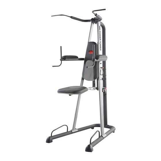
Thank you for selecting the versatile WEIDER reading this manual, please see the front cover of this CLUB™ 390 POWER TOWER exercise rack. The manual. To help us assist you, note the product model exercise rack is designed to develop the muscles of number and serial number before contacting us. -
Page 5: Part Identification Chart
All manuals and user guides at all-guides.com PART IDENTIFICATION CHART See the drawings below to identify small parts used in assembly. The number in parentheses by each drawing is the key number of the part, from the PART LIST near the end of this manual. Note: If a part is not in the hard- ware kit, check to see if it has been preattached. -
Page 6: Assembly
All manuals and user guides at all-guides.com ASSEMBLY • To hire an authorized service technician to • To identify small parts, see page 5. assemble the exercise rack in your home, call 1-800-445-2480. • The following tools (not included) may be required for assembly: •... - Page 7 All manuals and user guides at all-guides.com 2. Press the two Base Leg Caps (22) onto the Base Legs (2). Insert the two Base Legs (2) into the Base (1) as shown. Insert four M10 x 90mm Button Bolts (42) upward through the Base. Tip: It may be helpful to place tape over the bolt heads to hold them in place.
- Page 8 All manuals and user guides at all-guides.com 4. Attach the Rear Top Frame (6) to the Rear Upright (5) with two M10 x 85mm Button Bolts (51) and two M10 Locknuts (35). Do not tight- en the Locknuts yet. 5. Attach the Left Front Upright (50) to the Base (1) using the indicated M10 x 90mm Button Bolts (42) and two M10 Locknuts (35).
- Page 9 All manuals and user guides at all-guides.com 6. Slide the Front Top Frame (4) onto the Right and Left Front Uprights (3, 50). 7. Attach the Backrest Support (8) to the Rear Upright (5) with an M10 x 62mm Button Bolt (30) and an M10 Locknut (35).
- Page 10 All manuals and user guides at all-guides.com 8. Insert the Pull-up Frame (7) into the Rear Top Frame (6). Attach the Pull-up Frame (7) with four M8 x 15mm Button Screws (39) and two M8 x 62mm Button Screws (41). See steps 3–5, and 7.
- Page 11 All manuals and user guides at all-guides.com 11. Attach the Knee Pad Plate (14) and the Knee Pad (15) to the Pad Frame (11) with two M6 x 80mm Button Screws (47) and two M6 Washers (36). 12. Fully insert an Adjustment Pin (29) through the indicated hole in the Rear Upright (5) and through the Assist Arm (9).
- Page 12 All manuals and user guides at all-guides.com 14. Hold the Dip Arm (10) behind the Front Top Frame (4) as shown. Attach the Dip Arm (10) to the Front Top Frame (4) with two M10 x 100mm Button Bolts (31) and two M10 Locknuts (35).
- Page 13 All manuals and user guides at all-guides.com 17. Attach an Armrest Plate (18) and an Armrest (19) to the Dip Arm (10) with two M6 x 70mm Button Screws (45) and two M6 Washers (36). Attach the other Armrest (19) and Armrest Plate (not shown) in the same way.
-
Page 14: Adjustment
All manuals and user guides at all-guides.com ADJUSTMENT This section explains how to adjust the exercise rack. See the EXERCISE GUIDELINES on page 16 for impor- tant information about how to get the most benefit from your exercise program. Also, refer to the accompanying exercise guide to see the correct form for each exercise. - Page 15 All manuals and user guides at all-guides.com ADJUSTING THE KNEE PAD To adjust the Knee Pad (15) to the horizontal posi- tion, lift the Knee Pad so that the rod on the Assist Arm (9) is in the notch in the Pad Frame (11). Notch L-slot Then, lower the Knee Pad (15) so that the 5mm...
-
Page 16: Exercise Guidelines
All manuals and user guides at all-guides.com EXERCISE GUIDELINES FOUR TYPES OF STRENGTH WORKOUTS workout, and the numbers of repetitions and sets to complete. Progress at your own pace and be sensitive Note: A “repetition” is one complete cycle of an exer- to your bodyʼs signals. - Page 17 All manuals and user guides at all-guides.com NOTES...
-
Page 18: Part List
All manuals and user guides at all-guides.com PART LIST—Model No. WEBE2998.0 R1209A Key No. Qty. Description Key No. Qty. Description Base Pull-up Handle Cap Base Leg Adjustment Pin Right Front Upright M10 x 62mm Button Bolt Front Top Frame M10 x 100mm Button Bolt Rear Upright 25-pound Resistance Band Rear Top Frame... -
Page 19: Exploded Drawing
All manuals and user guides at all-guides.com EXPLODED DRAWING—Model No. WEBE2998.0 R1209A... -
Page 20: Ordering Replacement Parts
All manuals and user guides at all-guides.com ORDERING REPLACEMENT PARTS To order replacement parts, please see the front cover of this manual. To help us assist you, be prepared to provide the following information when contacting us: • the model number and serial number of the product (see the front cover of this manual) •...
Need help?
Do you have a question about the 390 POWER TOWER and is the answer not in the manual?
Questions and answers