Algodue ELETTRONICA UPM 3100 Manual
Universal power meter
Hide thumbs
Also See for UPM 3100:
- Use and programming manual (70 pages) ,
- Installation and configuration manual (36 pages)

Related Manuals for Algodue ELETTRONICA UPM 3100


Summary of Contents for Algodue ELETTRONICA UPM 3100
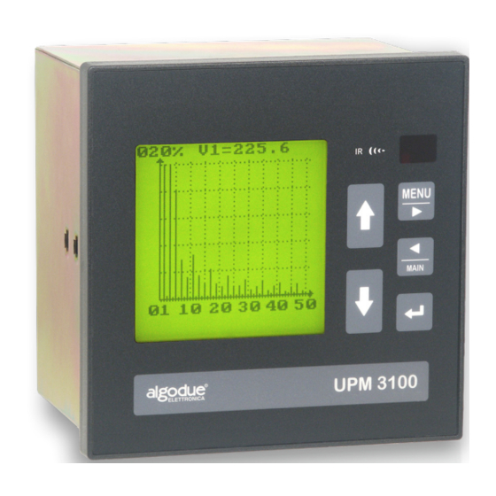
- Page 1 UPM 3100 Universal Power Meter EN50160 Energy quality Analysis English Rev. 01 - 2003...
-
Page 2: Table Of Contents
ENGLISH UPM 3100 General contents GENERAL CONTENTS ............A CHAPTER 1 INTRODUCTION ..............1-1 CHAPTER 2 GRAPHIC SYMBOLS ............2-1 CHAPTER 3 PRECAUTIONARY MEASURES ........3-1 CHAPTER 4 DESCRIPTION ..............4-1 FUNCTIONING ............4-2 4.1.1 MIN/AVG/MAX ............4-2 4.1.2 VDROP ..............4-3 CHAPTER 5 DISPLAYED DATA ............. -
Page 3: Introduction
ENGLISH UPM 3100 1. Introduction This Manual is not intended for general use, but for qualified technicians. This term indicates a professional and skilled technician, authorised to act in accordance with the safety standards relating to the dangers posed by electric current. - Page 4 ENGLISH UPM 3100 The information contained in this manual and in the Installation and Configuration Manual was carefully checked at the time of publication. However, the Manufacturer does not accept liability for any inaccuracy, errors, missing updates, and reserves the right to modify the device and / or documentation without prior notice.
-
Page 5: Graphic Symbols
ENGLISH UPM 3100 2. Graphic symbols Some instructions in the Manual and on the device are highlighted by graphic symbols to draw the reader’s attention to the operational dangers. The following graphic symbols are used: DANGER ! This warning indicates the possible presence of voltage higher than 1kV on the marked terminals (even for short periods). -
Page 6: Precautionary Measures
ENGLISH UPM 3100 3. PRECAUTIONARY MEASURES In standard operation mode, the instrument is connected with power sources that are potentially dangerous for operators. The connecting terminals of the power supply cables, the voltage and current transformers and the digital and analog inputs and outputs are powered. -
Page 7: Description
ENGLISH UPM 3100 4. DESCRIPTION The device equipped with the CPU2 option assures the continuous sampling of the measured values. The CPU2 can store the following data in its RAM: - Any detected voltage anomalies (VDROP); - Minimum, Average and Maximum values of 10 variables, selected among those measured by the device. -
Page 8: Functioning
ENGLISH UPM 3100 FUNCTIONING 4.1.1 MIN/AVG/MAX This function assures the continuous sampling of the variables and can be used to record the minimum, medium and maximum values of the programmed variable in order to carry out the mains quality analysis in compliance with the EN50160 norms. -
Page 9: Vdrop
ENGLISH UPM 3100 4.1.2 VDROP In compliance with the reference norm EN50160, the following voltage anomalies can be measured and recorded thanks to the VDROP record: - Fast voltage variation Fast increase or decrease of voltage up to 10% of the nominal voltage. - Page 10 ENGLISH UPM 3100 ACQUISITION WITH FIXED REFERENCE VOLTAGE In this mode of operation, the reference voltage used for threshold values calculation is fixed and as the same value of preset nominal voltage (Pict. 1.3.2). The high and low threshold values are expressed as percentages of the reference value.
-
Page 11: Displayed Data
ENGLISH UPM 3100 5. DISPLAYED DATA INFO PAGE When the CPU2 option is included, on the LCD graphic display an additional info PAGE shows the recordings information. VDROP RECORDING On the page the values of phase 1, 2 and 3 are displayed alternatively. -
Page 12: Programming
ENGLISH UPM 3100 6. PROGRAMMING If the CPU2 is selected in the programming page of the device, the displayed page allows the user to select the VDROP or MIN/AVG/MAX recording. When moving from one recording mode to another, the selection confirmation page is displayed: Pict. -
Page 13: Vdrop
ENGLISH UPM 3100 VDROP Page for programming the recording of voltage faults, when the VDROP option is included. -Vnom (%FS) This value is expressed as a percentage of the programmed full scale value (433V). The number just below is the actual value, which is calculated automatically. -
Page 14: Digital Output
ENGLISH UPM 3100 6.1.1 DIGITAL OUTPUT If the digital option is installed, voltage drops may be signaled through the digital output. The operation is monostable, i.e. after the event takes place the output is on (closed) for a programmable time interval ranging from 1 to 10 seconds. -
Page 15: Min/Avg/Max
ENGLISH UPM 3100 MIN/AVG/MAX - Parameters The values which can be stored are sequentially shown; - select parameters; - storage enabled/disabled. Note: max. 10 variables can be Pict.6.2.1 - MIN/AVG/MAX setup simultaneously stored. - Time AVG Integration time in seconds for the calculation of the medium value; it is also the storage interval of the minimum and maximum values. - Page 16 ENGLISH UPM 3100 - Recording Delay Storage delayed start, expressed in hours and minutes. Programmable range from 00:00 to 23:59. This parameter can be programmed only after selecting the STACK storage mode. - Erase RAM Displays the cancellation confirmation box for the file stored in the CPU2 RAM.
-
Page 17: Technical Specifications
ENGLISH UPM 3100 7. TECHNICAL SPECIFICATIONS VDROP: Connection: 4 connection wires with neutral + single phase. Voltage: 433 VAC max. L-N (750 VAC L-L). Measurement mode: continuous sampling of the three phases RMS value is calculated every 10 ms. Measurement frequency: 45-65 Hz. - Page 18 ENGLISH UPM 3100 MEMORY: Values which are recorded for each event: VDROP - Date and time of fault start. - The fault type: vdrop or overvoltage. - The phase (L1-N, L2-N, L3-N). - The minimum or the maximum values measured.
-
Page 19: Wintool Software
ENGLISH UPM 3100 8. WINTOOL SOFTWARE The WINTOOL software is supplied with the instrument. This software detects automatically if the CPU2 option is included. It is used to program the instrument and transfer the data to the PC. PROGRAMMING To enter the CPU2 programming window select the proper button in the... -
Page 20: Vdrop Setup
ENGLISH UPM 3100 VDROP SETUP The following box is displayed when is selected: - EN 50160 Setup Activating this function, the lowest threshold and the integration time are programmed automatically to the standards. The field which can be modified contain values not specified in the standard. - Page 21 ENGLISH UPM 3100 - High Threshold [+%Vn] High threshold. Over this value overvoltage is recorded. This value is expressed as a percentage variation of the programmed reference value (ranging from +1% to +99%.). The number its side is the actual value, which is calculated automatically.
-
Page 22: Digital Output
ENGLISH UPM 3100 8.2.1 DIGITAL OUTPUT In case of VDROP recording, the voltage anomalies can be signalled by enabling the digital output (if available). Select in the PROGRAMMING PAGE of the instrument the function to enter the programming windows for Inputs/Outputs, when the instrument is fitted with them. -
Page 23: Min/Avg/Max
ENGLISH UPM 3100 MIN/AVG/MAX The following box is displayed when the CPU2 MIN/AVG/MAX mode is selected: - EN 50160 Setup The MED Time (060s) and parameter (V1, V2, V3) values are automatically programmed when this function is enabled, in compliance with the norms. - Page 24 ENGLISH UPM 3100 Selects the RAM storage method of the MIN/AVG/MAX values as follows: - FIFO - storage of the latest data, by overwriting the old data; - STACK - data storage until the RAM is full. - Recording Delay Storage delayed start, expressed in hours and minutes.
-
Page 25: Download
ENGLISH UPM 3100 DOWNLOAD With the WINTOOL program, you can transfer the data from your instrument to the PC. On this dialog window you can select which data recorded in the instrument should be transferred to the Hard Disk of the PC. - Page 26 ENGLISH UPM 3100 The dialog box appearing at the end of the transferring allows to save the file in the desired directory with the desired name. After having stored the files on the Hard Disk WINTOOL shows a dialog box asking for the confirmation to delete the transferred data from the instrument.
- Page 30 via Passerina, 3 / A - 28010 FONTANETO D’AGOGNA (NO) - ITALY Tel. + 39 0322 89864 / 89307 / 89871 (fax) Internet: http://www.algodue.com - E-mail: info@algodue.com WARNING - ALGODUE declines all liability for any damage to people or property caused by incorrect use of this product.
Need help?
Do you have a question about the UPM 3100 and is the answer not in the manual?
Questions and answers