Table of Contents
Advertisement
Quick Links
1. INTRODUCTION
This manual provides information on the installation, configuration and use of the main instrument functions.
The manual is not intended for general use, but for qualified technicians.
This term indicates a professional and skilled technician, authorised to act in accordance with the safety
standards relating to the dangers posed by electric current.
This person must also have basic first aid training and be in possession of suitable Personal Protective
Equipment.
WARNING!
It is strictly forbidden for anyone who does not fulfill the above-mentioned requirements
to install or use the instrument.
The instrument complies with the European Union directives in force, as well as with the technical standards
implementing these requirements, as certified by the CE mark on the device and on this Manual.
Using the meter for purposes other than intended ones, understood by the manual content, is strictly
forbidden. The information herein contained shall not be shared with third parties. Any duplication of this
manual, either partial or total, not authorised in writing by the Manufacturer and obtained by photocopying,
duplicating or using any other electronic means, violates the terms of copyright and is punishable by law.
Any brands quoted in the publication belong to the legitimate registered owners.
NOTE. This manual describes the use of the main instrument functions.
UPM307
UNIVERSAL POWER METER
USER MANUAL
Advertisement
Table of Contents

Related Manuals for Algodue ELETTRONICA UPM307


Summary of Contents for Algodue ELETTRONICA UPM307
- Page 1 UPM307 UNIVERSAL POWER METER USER MANUAL 1. INTRODUCTION This manual provides information on the installation, configuration and use of the main instrument functions. The manual is not intended for general use, but for qualified technicians. This term indicates a professional and skilled technician, authorised to act in accordance with the safety standards relating to the dangers posed by electric current.
-
Page 2: Graphic Symbols
The basic instrument can be customized with some options to fit to the specific application. The UPM307 is a compact, cost effective meter operating both as a stand-alone device or as part of a more extensive energy monitoring and management network. -
Page 3: Installation
5. INSTALLATION NOTE. The equipment complies with the 89/366/EEC, 73/23/EEC standards and following amendments. However, if not properly installed, it may generate a magnetic field and radio interference. This is why compliance with EMC standards on electromagnetic compatibility is essential. 5.1 ENVIRONMENTAL REqUIREMENTS The environment in which the instrument is installed must satisfy the following features: •... -
Page 4: Safety Measures
6. SAFETY MEASURES DANGER! This warning means that a voltage exceeding 1kV (even if for short periods) may be present on the terminals. WARNING! Electrical instrument connections must be carried out only by skilled technicans who are aware of the risks involved to the presence of voltage. Before connecting, check the following: 1. -
Page 5: Profibus Version
PROFIBUS VERSION ETHERNET VERSION The connections are made on the back side of the instrument according to the following order. 1. Digital outputs. See section 7.5 2. Communication port (optional). See section 7.1 3. Power supply. See section 7.7 4. Current inputs. See section 7.6 5. - Page 6 7.1.2 RS 485 The easiest and cheapest way to connect different measuring devices in a network is the RS485 serial line. The RS485 standard interface allows a multi-point connection. Between PC and the network, it is required a Serial RS232 to RS485 Converter. If more than 32 instruments are to be connected, insert a signal repeater. Each repeater can manage up to 32 instruments.
- Page 7 7.3 RS485 PROFIBUS COMMUNICATION PORT (optional) The PROFIBUS interface allows a point to point connection: i.e. instrument to PC or other device. For the connection use a STD cable for PROFIBUS connection with a 9-pole male connector on the device side. If the standard cable for PROFIBUS is not available, produce one according to the scheme in the picture.
- Page 8 7.4 ETHERNET COMMUNICATION PORT (optional) The ETHERNET interface allows a connection between the instrument and an ETHERNET network. For the connection use an HUB or a Switch. If the instrument is set on STANDARD protocol and it is connected to the network, all instrument measurements can be displayed remotely on a PC by typing the IP address of the instrument ETHERNET interface in the web address field.
-
Page 9: Digital Outputs
7.5 DIGITAL OUTPUTS The instrument is equipped with two digital outputs. The digital outputs can be programmed for alarm tripping or energy pulse emission. WARNING! Before connecting or disconnecting the digital outputs, be sure that the instrument is not powered. The power supply line, the measurement inputs and any other voltage source must be disconnected. -
Page 10: Voltage And Current Inputs
7.6 VOLTAGE AND CURRENT INPUTS Connect the voltage and current inputs according to the pictures below. NOTE. In case of Rogowski coils, please check that YELLOW cable edge is connected to S1 (signal) and the WHITE cable edge is connected to S2 (common). 3 phases, 4 wires, 3 current transformers (3.4.3) direct connection connection with voltage transformer... - Page 11 3 phases, 3 wires, 1 current transformer (3.3.1) direct connection connection with voltage transformer 3 phases, 2 wires, 1 current transformer (3.2.1) direct connection connection with voltage transformer 1 phase (1ph) direct connection...
-
Page 12: Power Supply
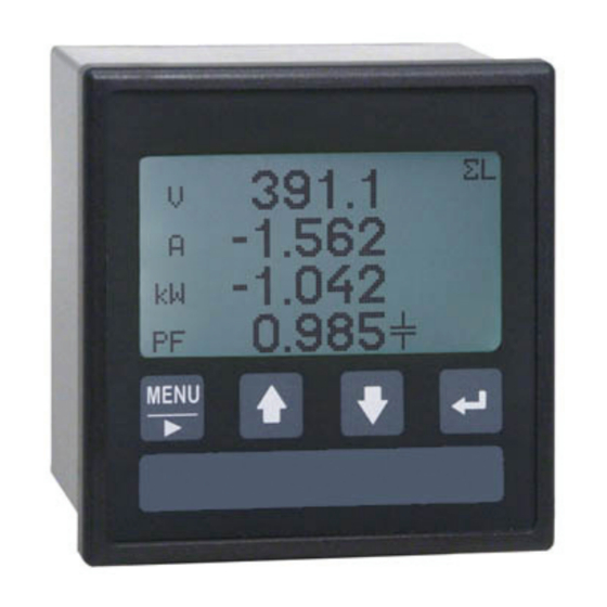
WARNING! Check that: 1. if the instrument must carry out bi-directional measurements to obtain correct measurements, the connections must respect the polarities. 2. the connections are made according to the diagrams in the following section, respecting the cyclic order of phases (important: L1 of the voltage input = L1 of the current input) 3. - Page 13 8. USE AND CONFIGURATION NOTE. The chapter describes the main configuration parameters of the standard version of the meter. The pages described in this manual refer to the instrument set in 3-PHASE,4-WIRE/3CT wiring mode. Some pages may differ or disappear if the wiring mode is different. 8.1 CONTROL PANEL DESCRIPTION The front LCD shows all the parameters measured by the instrument in a numeric format.
- Page 14 8.3 GENERAL MENU To display the General Menu, press for at least 2 seconds MENU key. To enter one of the following section, move the highlighted bar to the requested item by means of UP or DOWN key and press ENTER key. INSTANTANEOUS Instantaneous values.
- Page 15 To display the General Menu, from any Setup page, press MENU key for at least 2 seconds. If a parameter has been changed previously, a warning message will be displayed. The instrument requests confirmation to save the new data. Available choices: •...
- Page 16 DMD Time (demand integration time) This function allows to set the integration time for demand calculation. 8.4.2 Communication It allows to set the communication parameters. To enter this section, move the highlighted bar to COMMUNICATION by means of UP or DOWN key and press ENTER key. To set the parameters, see section 8.4.5 Protocol The available protocols are:...
- Page 17 8.4.3 Digital Out The basic instrument is equipped with two digital outputs. To enter this section, move the highlighted bar to DIGITAL OUT by means of UP or DOWN key and press ENTER key. It is displayed a list of the available digital outputs.
- Page 18 The result can be rounded off to a higher value for an easier calculation or totalization of the energy consumption. For example 1, it is possible to select 1.5, 2 or 10 kWh/p. For example 2, it is possible to select 0.5 or 1 kWh/p. The pulse emission frequency will be proportionally lower.
- Page 19 Clear Counters This function allows to clear the energy counters. To reset the values, press ENTER key when the highlighted bar is on CLEAR COUNTERS. The instrument requests confirmation to clear data. Available choices: • reset data; before clearing, the instrument requests the password: insert it within 5 s, pressing UP and DOWN keys simultaneously.
-
Page 20: Menu Structure
8.5 MENU STRUCTURE The following page shows the General Menu structure. To enter any page, move the cursor to the requested item and press ENTER key. -
Page 21: Maintenance
9. CORRECT CONFIGURATION CHECK If the meter configuration or wiring is not properly set, one of the following problems may occur: A. The three phases have a negative sign 1. Check the direction of current, indicated by the arrow on each measurement CT: turn the CT by 180° or reverse the CT connection if necessary (this solution is also recommended for a single-phase connection) B. -
Page 22: Technical Features
11. TECHNICAL FEATURES POWER SUPPLY VOLTAGE Rated voltage A) 115 V +15% -20% B) 230 V +15% -20% C) 65÷250 V / 90÷250 V R) 19÷60 V Consumption 2 VA max Fuse type T (delayed) - 100mA (to be mounted externally) VOLTAGE INPUT Max voltage (VL-L) 600 (750) VAC L-L... - Page 23 MECHANICAL FEATURES Material NORYL UL 94 V-0 self-extinguishing plastic case - Black Protection degree IP54 (front panel) - IP20 (terminals) Terminals wire 2.5 mm - 10 A rating Size (mm) 96x96x60 (with rated voltage A-B), 96x96x100 (with rated voltage C-R) Weight 300g max (with rated voltage A-B), 500g max (with rated voltage C-R) STANDARDS COMPLIANCE...
Need help?
Do you have a question about the UPM307 and is the answer not in the manual?
Questions and answers