
Related Manuals for Algodue ELETTRONICA UPM307


Summary of Contents for Algodue ELETTRONICA UPM307
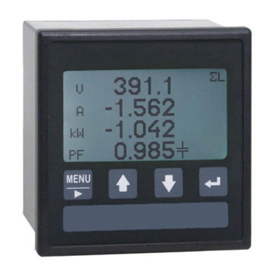
- Page 1 UPM307 DIN 96x96 Compact Power Meter Universal Power Meter MODBUS protocol manual English Rev. 008 - 10/07/2012...
-
Page 2: Table Of Contents
MODBUS protocol manual ENGLISH Table of conTenTs 1. InTRoDUcTIon ...............1-1 2. sYMbols ................2-1 3. DescRIPTIon ..............3-1 3.1 LRC generation ................3-3 3.2 CRC generation ................3-4 4. ReaD ReGIsTeRs ............4-1 4.1 Floating point as per IEEE Standard ........... 4-3 5. PaRaMeTeRs seTUP ............5-1 6. -
Page 3: Introduction
MODBUS protocol manual ENGLISH 1. IntroductIon This manual provides information on the MODBUS communication protocol. The publication is not intended for general use, but for qualified technicians. This term indicates a professional and skilled technician, authorised to act in accordance with the safety standards relating to the dangers posed by electric current. -
Page 4: Symbols
MODBUS protocol manual ENGLISH 2. SymbolS In the manual and on the device, some instructions are highlighted by symbols to draw the reader’s attention to the operational dangers. These symbols are the following: DANGER! This warning indicates the possible presence of voltage exceeding 1kV on the marked terminals (even for short periods). -
Page 5: Description
MODBUS protocol manual ENGLISH 3. Description MODBUS ASCII/RTU is a master-slave communication protocol, able to support up to 247 slaves connected in a bus or a star network. The protocol uses a simplex connection on a single line. In this way, the communication messages move on a single line in two opposite directions. - Page 6 MODBUS protocol manual ENGLISH coMMUnication fraMe strUctUre ascii mode Bit per byte: 1 Start, 7 Bit, Even, 1 Stop (7E1) Name Length Function START FRAME 1 char Message start marker. Starts with colon “:” ($3A) ADDRESS FIELD 2 chars Instrument logical number FUNCTION CODE 2 chars Function code ($03=read command, $10=write command)
-
Page 7: Lrc Generation
MODBUS protocol manual ENGLISH 3.1 Lrc generation The Longitudinal Redundancy Check (LRC) field is one byte, containing an 8–bit binary value. The LRC value is calculated by the transmitting device, which appends the LRC to the message. The receiving device recalculates an LRC during receipt of the message, and compares the calculated value to the actual value it received in the LRC field. -
Page 8: Crc Generation
MODBUS protocol manual ENGLISH 3.2 crc generation The Cyclical Redundancy Check (CRC) field is two bytes, containing a 16–bit value. The CRC value is calculated by the transmitting device, which appends the CRC to the message. The receiving device recalculates a CRC during receipt of the message, and compares the calculated value to the actual value it received in the CRC field. - Page 9 MODBUS protocol manual ENGLISH taBLe crc generation fUnctions All of the possible CRC values are preloaded into two arrays, which are simply indexed as the function increments through the message buffer. One array contains all of the 256 possible CRC values for the high byte of the 16–bit CRC field, and the other array contains all of the values for the low byte.
- Page 10 MODBUS protocol manual ENGLISH unsigned short ModBus_CRC16( unsigned char * Buffer, unsigned short Length ) unsigned char CRCHi = 0xFF; unsigned char CRCLo = 0xFF; Index; unsigned short ret; while( Length-- ) Index = CRCLo ^ *Buffer++ ; CRCLo = CRCHi ^ CRC_Table_Hi[Index]; CRCHi = CRC_Table_Lo[Index];...
-
Page 11: Read Registers
MODBUS protocol manual ENGLISH 4. Read RegisteRs (Function code $03) The master communication device can send commands to the instrument to read its measured values, status and setup. More registers can be read, at the same time, sending a single command, only if the registers are consecutive. - Page 12 MODBUS protocol manual ENGLISH MOdBUs tCP Values contained both in Query or Response messages are in hexa format. Query example in case of MODBUS TCP: 01000000000D010300000004 example Byte description No. of bytes Transaction identifier High Protocol identifier High Byte count Unit identifier Function code High...
-
Page 13: Floating Point As Per Ieee Standard
MODBUS protocol manual ENGLISH 4.1 Floating point as per ieee standard (not available for MOdBUs tCP) The basic format allows a IEEE standard floating-point number to be represented in a single-32 bit format, as shown below: N.n = (-1) (1.f ) e’-127 where S is the sign bit, e’... - Page 14 MODBUS protocol manual ENGLISH exaMPle OF CONveRsiON OF valUe shOwN with FlOatiNg POiNt Value read with floating point: 45AACC00( Value converted in binary format: 010001011 01010101100110000000000 ( exponent fraction sign sign = 0 exponent = 10001011( ) = 139( fraction = 01010101100110000000000( ) / 8388608 ( = 2804736 ( ) / 8388608 (...
-
Page 15: Parameters Setup
MODBUS protocol manual ENGLISH 5. Parameters setuP (Function code $10) The master communication device can send commands to the instrument to program it. More settings can be carried out, at the same time, sending a single command, only if the relevant registers are consecutive. - Page 16 MODBUS protocol manual ENGLISH mODBus tCP Values contained both in Request or Response messages are in hexa format. Query example in case of MODBUS TCP: 0100000000090110E0280001020007 example Byte Description No. of bytes Transaction identifier High Protocol identifier High Byte count Unit identifier Function code High...
-
Page 17: Exception Codes
MODBUS protocol manual ENGLISH 6. EXCEPTION CODES When the instrument receives a not-valid query, an error message (exception code) is sent. According to the used MODBUS protocol mode, possible exception codes are as follows. MODBUS ASCII/RTU Values contained in Response messages are in hexa format. Response example in case of MODBUS ASCII/RTU: 0183000131F0 Example Byte... - Page 18 MODBUS protocol manual ENGLISH MODBUS TCP Values contained in Response messages are in hexa format. Response example in case of MODBUS TCP: 010000000003018302 Example Byte Description No. of bytes Transaction identifier High Protocol identifier High No. of byte of next data in this string Unit identifier Function code (80+03) Exception code...
-
Page 19: Registers Table
MODBUS protocol manual ENGLISH 7. RegisteRs table 7.1 important notes for registers NOte the highest number of registers, which can be read with a single command, are: - asCii mode: 63 registers - RtU mode: 127 registers - tCP mode: 248 bytes NOte the highest number of registers, which can be programmed with a single command, are: - asCii mode: 13 registers... -
Page 20: Measured Values
MODBUS protocol manual ENGLISH 7.2 Measured values (Function code $03) Reg. Word Reg. Word Description U. M. sign (ieee) (ieee) $0000 $1000 SYSTEM VOLTAGE [mV] (Unsigned, MSB=0) $0004 $1002 L-N VOLTAGE PHASE 1 [mV] (Unsigned) $0008 $1004 L-N VOLTAGE PHASE 2 [mV] (Unsigned) $000C... - Page 21 MODBUS protocol manual ENGLISH Reg. Word Reg. Word Description U. M. sign (ieee) (ieee) $00A8 $1054 VOID (Unsigned) $00AC $1056 VOID (Unsigned) $00B0 $1058 IMPORTED REACTIVE CAPACITIVE ENERGY [mvarh] (Unsigned) $00B4 $105A EXPORTED REACTIVE CAPACITIVE ENERGY [mvarh] (Unsigned) $00B8 $105C IMPORTED APPARENT ENERGY [mVAh] (Unsigned)
- Page 22 MODBUS protocol manual ENGLISH The following registers are available only in Read Only (RO) mode. This mode is not programmable via serial port but it must be set manually on the instrument. Reg. Word Description U. M. Format $0030 SYSTEM APPARENT POWER [0.1kVA] (Signed 32bit) $0032 PHASE 1 POWER FACTOR...
- Page 23 MODBUS protocol manual ENGLISH High-Order Register register =value/10000 high Low-Order Register register =value modulus10000 The 32-bit value can be retrieved by the following calculation: value=register x 10000 + register high Example Value 12345678 is passed in unsigned 32-bit Modulus-10000 format. Register : 1234 = 04D2 Hex high...
-
Page 24: Harmonics Values
MODBUS protocol manual ENGLISH 7.3 Harmonics values * (Function code $03) Reg. Word Reg. Word Description U. M. sign (ieee) (ieee) $0300 $8200 HARMONIC - PHASE 1 VOLTAGE [m%] (Unsigned) $0304 $8202 HARMONIC - PHASE 1 VOLTAGE [m%] (Unsigned) $0308 $8204 HARMONIC - PHASE 1 VOLTAGE [m%]... - Page 25 MODBUS protocol manual ENGLISH Reg. Word Reg. Word Description U. M. sign (ieee) (ieee) $0558 $832C HARMONIC - PHASE 1 CURRENT [m%] (Unsigned) $055C $832E HARMONIC - PHASE 1 CURRENT [m%] (Unsigned) $0560 $8330 HARMONIC - PHASE 1 CURRENT [m%] (Unsigned) $0564 $8332...
-
Page 26: Read Only Parameters
MODBUS protocol manual ENGLISH 7.4 Read only parameters (Function code $03) Register Word Description Range/Values $E000 SERIAL NUMBER 10 ASCII characters, do not consider the first one $E005 VERSION NUMBER 14 ASCII characters, do not consider the first tenth $E00C INSTRUMENT MODEL CODE $0013 (fixed for this model) $E00F... - Page 27 MODBUS protocol manual ENGLISH Register Word Description Range/Values Reset $E03C DMD INTEGRATION TIME (in minutes) $0001 $0003 $0005 $000A $000F $001E $003C $E03D BACKLIGHT ON TIME (000÷999 sec.) $0000÷$03E7 $E03F LANGUAGE 0=English 1=Deutsch 2=Français $E0A0 COUNTERS RESET 0=none 1=reset all energy counters 5=reset hours counter * $E0A1 PEAK RESET...
- Page 28 MODBUS protocol manual ENGLISH Register Word Description Range/Values Reset Pulse mode The register is structured in 5 different parameters and $E100 each one corresponds to 1 word. VARIABLE (see section 7.6) $00XX MODE 3=pulse (fixed) PULSE DURATION (150 msec) $0096 (fixed) PULSE COEFFICIENT (0÷999) $0000÷$03E7 (Ex.
-
Page 29: Variables List
MODBUS protocol manual ENGLISH 7.6 Variables list The code assigned to each variable is described in the following list. N. var. Description symbol System voltage VΣ L-N voltage phase 1 L-N voltage phase 2 L-N voltage phase 3 L-L voltage 12 L-L voltage 23 L-L voltage 31 System current... - Page 30 MODBUS protocol manual ENGLISH N. var. Description symbol System active power demand WΣDMD System apparent power demand VAΣDMD Phase 1 current demand A1DMD Phase 2 current demand A2DMD Phase 3 current demand A3DMD System current demand AΣDMD None variable selected Imported active energy Imported apparent energy +VAh...
- Page 32 Innovative Electronic Systems Via Passerina, 3/a - 28010 FONTANETO D’AGOGNA (NO) - ITALY http://www.algodue.com - support@algodue.com...
Need help?
Do you have a question about the UPM307 and is the answer not in the manual?
Questions and answers