Algodue ELETTRONICA UPM3100 Use And Programming Manual
Universal power meter
Hide thumbs
Also See for UPM3100:
- Installation and configuration manual (36 pages) ,
- Manual (30 pages)

Subscribe to Our Youtube Channel
Related Manuals for Algodue ELETTRONICA UPM3100


Summary of Contents for Algodue ELETTRONICA UPM3100
- Page 1 UPM3100 Universal Power Meter Use and Programming Manual English Rev. 008 - 11/12/2009 www.algodue.com...
-
Page 2: Table Of Contents
Use and Programming Manual ENGLISH TABLE OF CONTENTS INTRODUCTION SYMBOLS PRECAUTIONS USING THE INSTRUMENT General Overview Keypad MENU Menu Structure Instantaneous 5.2.1 List of Pages 5.2.2 Symbols 5.2.3 Power Factor Compensation 5.2.4 Displayed Pages Energy Counters 5.3.1 List of Pages DMD&Peak 5-11 5.4.1 List of Pages... - Page 3 Use and Programming Manual ENGLISH Utility Setup 5-20 5.9.1 Contrast Adjustment 5-20 5.9.2 Clear Counters 5-20 5.9.3 Clear Min/Max 5-21 5.9.4 Clear Records 5-21 5.9.5 Clear Demands 5-21 5.9.6 Clear DMD Peaks 5-22 5.9.7 Set Default 5-22 5.10 Info 5-23 5.10.1 List of Pages 5-23 PROGRAMMING...
- Page 4 Use and Programming Manual ENGLISH Input / Output 6-17 6.9.1 Digital Outputs 6-17 6.9.2 Digital Inputs 6-18 6.9.3 Analog Outputs 6-18 6.9.4 Remarks on Value Programming 6-19 6.9.5 Fullscale Defi nition 6-19 6.9.6 Pulse Value Calculation 6-20 6.10 CPU2 - Power Quality 6-21 6.10.1 VDROP 6-22...
-
Page 5: Introduction
Use and Programming Manual ENGLISH 1. INTRODUCTION This manual enables the instrument to be installed, confi gured and used in its main functions. A second manual with advanced features may be found in the CD ROM in the box. Both publications are not intended for general use, but for qualifi ed technicians. By this term, a professional fi... -
Page 6: Symbols
Use and Programming Manual ENGLISH 2. GRAPHIC SYMBOLS In the manual and on the instrument, some instructions are highlighted by graphic symbols to draw the reader’s attention to the operational dangers. The following graphics are used: DANGER! This warning indicates the possible presence of voltage exceeding 1kV on the marked terminals (even for short periods). -
Page 7: Precautions
Use and Programming Manual ENGLISH 3. PRECAUTIONS During normal operation the instrument is connected to sources of electrical voltage which are potentially dangerous for the operator. Voltage is present on the connection terminals of the power supply wires, on the voltage and current transformers, and on the digital and analog inputs and outputs. -
Page 8: Using The Instrument
Use and Programming Manual ENGLISH 4. USING THE INSTRUMENT 4.1 General Overview Infrared port Display Keypad 4.2 Keypad UP - DOWN keys Normal display mode a. Scroll up/down the pages or move the cursor to the available options Programming mode a. - Page 9 Use and Programming Manual ENGLISH ENTER key Normal display mode a. Confi rm the selection and display the selected function b. Pressed together with MAIN key, display the Main Page Programming mode a. Confi rm the entered selection b. Confi rm the modifi ed values USING THE INSTRUMENT...
-
Page 10: Menu
Use and Programming Manual ENGLISH 5. MENU To enter the General Menu, press MENU key for at least 3 seconds. 1. INSTANTANEOUS Section 5.2 2. ENERGY COUNTERS Section 5.3 3. DEMAND & PEAK Section 5.4 4. MIN/MAX Section 5.5 5. OSCILLOSCOPE Section 5.6 6. - Page 11 Use and Programming Manual ENGLISH General Menu MENU...
-
Page 12: Instantaneous
Use and Programming Manual ENGLISH 5.2 Instantaneous The pages in this section display the instantaneous values measured by the instrument. 1. Press and hold MENU key for at least 3 seconds. The General Menu will be displayed 2. Move the highlight bar to INSTANTANEOUS by means of UP and DOWN keys and press ENTER key 3. - Page 13 Use and Programming Manual ENGLISH MENU...
-
Page 14: Symbols
Use and Programming Manual ENGLISH Description: 1. System values (voltage, current, active power and power factor) 2. System active, reactive and apparent power 3. Line voltages and frequency 4. Phase voltages and phase order 5. Phase and neutral currents 6. Thermal current (ENH) 7. -
Page 15: Power Factor Compensation
Use and Programming Manual ENGLISH The fi gure below shows the geometric representation of active and reactive power and power factor, in compliance with the EN61268 Standard. Exported active power Imported active power Power factor (and COSφ) NOTES: 1. The chart refers to the current vector “I” (on the RH-side). 2. -
Page 16: Displayed
Use and Programming Manual ENGLISH 5.2.4 Displayed Pages The pages and the values displayed in the INSTANTANEOUS section can be different as they depend on the type of programmed wiring mode. See the following table. Wiring mode Description Var. System voltage System current System power factor System active power... - Page 17 Use and Programming Manual ENGLISH Wiring mode Description Var. Phase 1 active power Phase 2 active power Phase 3 active power Phase 1 reactive power var1 Phase 2 reactive power var2 Phase 3 reactive power var3 Phase 1 apparent power Phase 2 apparent power Phase 3 apparent power Phase 1 voltage THD...
-
Page 18: Energy Counters
Use and Programming Manual ENGLISH 5.3 Energy Counters The pages of this section display the energy counters. 1. Press and hold MENU key for at least 3 seconds. The General Menu will be displayed 2. Move the highlight bar to ENERGY COUNTERS by means of UP and DOWN keys and press ENTER key 3. - Page 19 Use and Programming Manual ENGLISH TOU - Time Of Use The instrument manages TOU energy counters divided into three programmable bands (Rates). There are 120 time of use counters, divided as follows: • 5 counters for imported energy and 5 counters for exported energy •...
-
Page 20: List Of
Use and Programming Manual ENGLISH 5.4 Demand&Peak The pages of this section display the demand and demand peak values. 1. Press and hold MENU key for at least 3 seconds. The General Menu will be displayed 2. Move the highlight bar to DEMAND&PEAK by means of UP and DOWN keys and press ENTER key 3. -
Page 21: Min / Max
Use and Programming Manual ENGLISH 5.5 Min / Max The pages of this section display the minimum and maximum values with date and time reference. 1. Press and hold MENU key for at least 3 seconds. The General Menu will be displayed 2. -
Page 22: Oscilloscope
Use and Programming Manual ENGLISH 5.6 Oscilloscope The pages of this section show the current and voltage waves of each phase. 1. Press and hold MENU key for at least 3 seconds. The General Menu will be displayed 2. Move the highlight bar to OSCILLOSCOPE by means of UP or DOWN keys and press ENTER key 3. -
Page 23: Harmonics
Use and Programming Manual ENGLISH 5.7 Harmonics The pages of this section show the current and voltage harmonic content. 1. Press and hold MENU key for at least 3 seconds. The General Menu will be displayed 2. Move the highlight bar to HARMONICS by means of UP and DOWN keys and press ENTER key 3. - Page 24 Use and Programming Manual ENGLISH 5-15 MENU...
-
Page 25: Under Limit Indication
Use and Programming Manual ENGLISH 5.7.2 UNDER LIMIT Indication The harmonic analysis is not performed when the voltage value is lower than the fullscale by 5% or when the current value is 1% lower than the fullscale. 5.7.3 Fullscale Setup To set the fullscale: 1. -
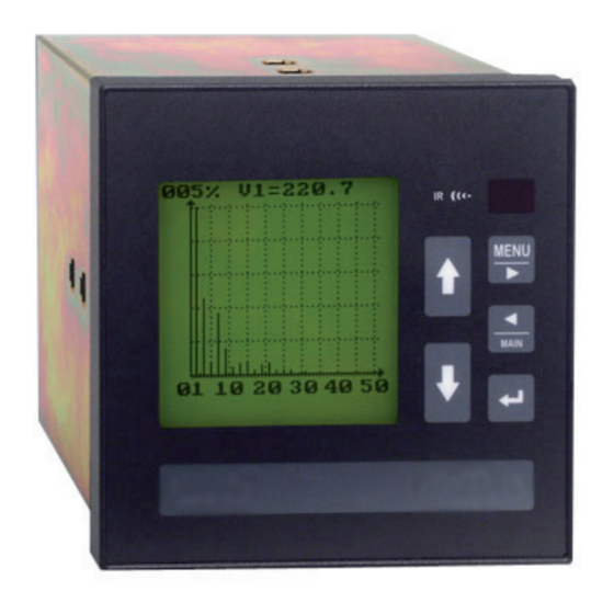
Page 26: Profiles
Use and Programming Manual ENGLISH 5.8 Profiles The pages of this section show the hystogram of minimum and maximum values. It is possible to display the current and the previous day graphics. 1. Press and hold MENU key for at least 3 seconds. The General Menu will be displayed 2. - Page 27 Use and Programming Manual ENGLISH Previous day Current day 5-18 MENU...
-
Page 28: Fullscale Setup
Use and Programming Manual ENGLISH 5.8.2 Fullscale Setup To set the fullscale: 1. Press ENTER key and a vertical cursor will be displayed 2. Press UP or DOWN key to increase or decrease the fullscale percentage (from 1 to 150) 3. -
Page 29: Utility Setup
Use and Programming Manual ENGLISH 5.9 Utility Setup The pages of this section allows to adjust the contrast and carry out the reset of the recorded measurements. 1. Press and hold MENU key for at least 3 seconds. The General Menu will be displayed 2. -
Page 30: Clear Min/Max
Use and Programming Manual ENGLISH 5.9.3 Clear Min/Max This function allows to clear the minimum and maximum values. 1. Move the highlight bar to CLEAR MIN/MAX by means of UP and DOWN keys and press ENTER key 2. The instrument will ask a further confi rmation displaying a message. By means of UP and DOWN keys select: •... -
Page 31: Clear Dmd Peaks
Use and Programming Manual ENGLISH 5.9.6 Clear DMD Peaks This function allows to clear the demand peak values. 1. Move the highlight bar to CLEAR DMD PEAKS by means of UP and DOWN keys and press ENTER key 2. The instrument will ask a further confi rmation displaying a message. By means of UP and DOWN keys select: •... -
Page 32: Info
Use and Programming Manual ENGLISH 5.10 Info The pages of this section show the main configuration and the operating conditions of the instrument. 1. Press and hold MENU key for at least 3 seconds. The General Menu will be displayed 2. -
Page 33: Programming
Use and Programming Manual ENGLISH 6. PROGRAMMING To enter the Setup Menu from the General Menu, move the highlight bar to SETUP, press ENTER key and the warning messages will be displayed; select YES and press ENTER key for both messages. -
Page 34: Access And Exit From Setup Menu
Use and Programming Manual ENGLISH 6.1 Access and Exit from Setup Menu 6.1.1 Access The procedure, described in this section, allows to enter the Setup Menu. 1. In General Menu, move the highlight bar to SETUP by means of UP and DOWN keys and press ENTER key 2. -
Page 35: Exit
Use and Programming Manual ENGLISH 6.1.2 Exit To exit from Setup Menu, press and hold MENU key for at least 3 seconds. The instrument will display a confi rmation window to save the modifi ed values. By means of UP and DOWN keys, select: •... - Page 36 Use and Programming Manual ENGLISH Setup Menu PROGRAMMING...
-
Page 37: Main Parameters
Use and Programming Manual ENGLISH 6.3 Main Parameters This section allows to confi gure the main operating parameters of the instrument. 1. In Setup Menu, move the highlight bar to MAIN PARAMETERS by means of UP and DOWN keys and press ENTER key 2. - Page 38 Use and Programming Manual ENGLISH Wiring The available wiring diagrams are: • 3-4-3 = 3 phases, 4 wires, 3 CTs • 3-3-3 = 3 phases, 3 wires, 3 CTs • 3-3-2 = 3 phases, 3 wires, 2 CTs • 3-3-1 = 3 phases, 3 wires, 1 CTs •...
-
Page 39: Display
Use and Programming Manual ENGLISH NOTE The parameters, set in «Main Parameters» section, are reset in any one of the following cases: • when the instrument is switched ON • after exiting the Setup section • after programming the operating parameters using the PC In order to obtain real demand values, wait for the entire length of the integration time. -
Page 40: Communication
Use and Programming Manual ENGLISH In this page, the same parameter cannot be set twice. To set the parameters, follow the same procedure described at point 3. 6.5 Communication This section allows to set the communication parameters of the instrument serial ports. 1. -
Page 41: Memory
Use and Programming Manual ENGLISH 6.6 Memory This section allows to set data recording and Event LOG mode (ENH). It is possible to program up to 10 recordings. All recorded data is stored in memory fi les and when the memory is full, all recordings in progress are immediately stopped. 1. -
Page 42: File Information
Use and Programming Manual ENGLISH RECORDING TYPE SAMPLING TIME PARAMETERS DMD POWER 1, 5, 10, 15, 30, 60 minutes programmable Programmable: WDMD, VADMD, varLDMD, varCDMD Programmable from 1 to 9999 minutes Programmable: V; V1; V2; V3; A; A1; A2; A3; MINIMUM / MAXIMUM W;... -
Page 43: New File
Use and Programming Manual ENGLISH 6.6.3 New File Up to 10 fi les can be stored in the memory. Type Select the type of data to be stored: DMD Pwr, Min/Max, Harm, InstVal Status Enable/ disable the recording: ON, OFF S. -
Page 44: Event Log Mode
Use and Programming Manual ENGLISH 6.6.5 Event LOG Mode This function is available only in the Enhanced Package version. It allows to set the event LOG recording mode. Available modes: NONE The recording function is disabled RING The instrument records data continuously. When the memory space is fi lled in, the oldest data is overwritten by the new data FILL The instrument records data up to fi... -
Page 45: Format
Use and Programming Manual ENGLISH Hyst The hysteresis value is expressed in percentage of the threshold value (0 – 99%) The threshold value is expressed in percentage of the fullscale of the selected variable. The value is programmable up to 150% with two decimal fi gures. The number shown under the percentage value is the absolute value, calculated by the instrument (non programmable) 6.6.7 Format This function allows to delete all memory data. -
Page 46: Clock
Use and Programming Manual ENGLISH 6.7 Clock This section allows to set the instrument real time clock (RTC). 1. In Setup Menu, move the highlight bar to CLOCK by means of UP and DOWN keys and press ENTER key 2. Move the highlight bar to the requested line by means of UP and DOWN keys 3. -
Page 47: Time Of Use
Use and Programming Manual ENGLISH 6.8 Time Of Use This section describes Time of Use (TOU) programmable data recording. The TOU function stores the energy consumption in different registers according to the programmed time-scheme. A group of 120 registers gives the situation of the previous and current day, and of the previous and current month. -
Page 48: Holidays
Use and Programming Manual ENGLISH 6.8.1 Holidays Moreover, Holidays function is provided. It allows to set up to 20 different dates. All holidays are considered with tariff 3. To set Holidays, follow the procedure below: 1. To change a parameter, press ENTER key 2. -
Page 49: Input / Output
Use and Programming Manual ENGLISH 6.9 Input / Output This section allows to set the instrument inputs and outputs. The basic instrument is equipped with two digital outputs. Additional inputs and outputs can be installed by plugging optional boards in the empty slots. 1. -
Page 50: Digital Inputs
Use and Programming Manual ENGLISH Delay This parameter has a different meaning according to the selected mode as indicated below. • PULSE mode: pulse length expressed in ms (001...999 ms). • HIGH/LOW mode: switch ON delay time in seconds (switch OFF has no delay). Hyst Threshold hysteresis (0-99% of value). -
Page 51: Remarks On Value Programming
Use and Programming Manual ENGLISH It is the value of the selected variable corresponding to 20mA. The value is defi ned as a percentage of the fullscale (see section 6.9.5). The number shown under the percentage value is the absolute value and it is automatically calculated by the instrument. -
Page 52: Pulse Value Calculation
Use and Programming Manual ENGLISH POWER The power fullscale is the result of the voltage fullscale and the current fullscale multiplication: System power f.s. = Vf.s. x Af.s. x 1.73 Line power f.s. = (Vf.s. x Af.s.) / 1.73 Maximum percentage: 150% 6.9.6 Pulse Value Calculation The maximum pulse re-emission rate is 1 pulse/sec (3600 pulse/h). -
Page 53: Cpu2 - Power Quality
Use and Programming Manual ENGLISH 6.10 CPU2 - Power Quality (optional) The co-processor (CPU2) board perfoms the simultaneous high-resolution sampling of voltage and current, allowing the cycle-by-cycle power analysis for 50/60 Hz lines. CPU2 board supports different application as VDROP, VMAX, WCAP. The instrument, with this option, performs at the same time wattmeter functions, harmonic analysis, basic recording function and the selected cycle-by-cycle power analysis function. -
Page 54: Vdrop
Use and Programming Manual ENGLISH 6.10.1 VDROP Sags & swells detection on L-N or L-L voltages (in case of wiring mode without neutral) with half cycle resolution (10ms @ 50Hz) . Pre- and post-trigger logging (100+100 half cycles RMS values). The detected events are recorded and a relay output can be activated when a voltage anomaly occurs. - Page 55 Use and Programming Manual ENGLISH ACQUISITION WITH FIXED REFERENCE VOLTAGE In this mode, the reference voltage, used for threshold values calculation, is fi xed. The high and low threshold values are expressed as percentages of the reference voltage. The values of the thresholds are fi...
- Page 56 Use and Programming Manual ENGLISH PROGRAMMING Vnom (%FS) Voltage nominal value for the high and low threshold calculation. This value is expressed as a percentage of the fullscale value. The number shown under the percentage value is the absolute value and it is automatically calculated by the instrument.
-
Page 57: Min/Avg/Max
Use and Programming Manual ENGLISH The Var. fi eld changes according to the set wiring mode, as described in the following table. Var. with N without N VDR-1 V1-2 VDR-2 V2-3 VDR-3 V3-1 VDR-OR all phases all phases 6.10.2 MIN/AVG/MAX This function allows to record up to 10 parameters (selected among voltage, current, power, PF and frequency) with continuous sampling and 1 cycle minimum resolution for RMS calculation. -
Page 58: Wcap
Use and Programming Manual ENGLISH Example: T.AVG= 3 sec. Frequency= 50 Hz -> period duration 1/50=0.02 sec. T.RMS (max)= 3/(2*0.02)=75 (max number of programmable periods) Memo type Recording mode: RING=the instrument records data continuously. When CPU2 memory space is fi lled, the oldest data is overwritten by the new data FILL=the instrument records data up to fi... - Page 59 Use and Programming Manual ENGLISH PROGRAMMING Mode Selection of voltage or current threshold mode Vnom or Anom Nominal value of voltage or current HT (+%Vn) High threshold. This value is expressed as a percentage of the nominal value (from +1% to max%, where «max%» depends on the nominal voltage value and the absolute value of the high threshold cannnot be higher than 150% of the fullscale).
- Page 60 Use and Programming Manual ENGLISH Samp./Wave - Number of samples/wave. Available values: 08, 16, 32 samples (depending on the number of waves set to be recorded before and after trigger). Waves After Trigger up to 50 up to 100 up to 200 Samples/wave Erase RAM - Erase all the values in CPU2 memory.
-
Page 61: Technical Features
Use and Programming Manual ENGLISH 7. TECHNICAL FEATURES 7.1 Available Options The instrument can be supplied, on request, with the Enhanced Package version or with further options, as shown in the following table: CONFIGURATION AND OPTIONS Serial interface RS232 / RS485 Power supply 65-250 V or 90-250 V 2 Digital Outputs... -
Page 62: Technical Data
Use and Programming Manual ENGLISH 7.2 Technical Data Auxiliary power supply voltage 65 - 250 V 50 / 60 Hz or 90 - 250 V On request 19 - 60 V Consumption: 18 VA (relating to the mounted options) Fuse: T type, 315mA (to be mounted externally) Safety conditions The instrument has been made and tested in compliance with the CEI EN61010-1 (1993) standard plus variation CEI EN61010-1/A2 (1995) and UL 61010A-1 (2002) for operating voltage up to 600... - Page 63 Use and Programming Manual ENGLISH Harmonic analysis Up to 50th order with FFT method on 3 voltages (V1, V2, V3) and 4 currents (A1, A2, A3, AN, neutral current available only with ENH version) simultaneously. Absolute and percentage values calculation. Measurement refresh: 3 seconds approximately for harmonics and THD Serial output RS232 / RS485 selectable by dip-switches.
- Page 64 Use and Programming Manual ENGLISH Display Backlight LCD graphic display 128x128 pixels. Backlight life: > 100.000 hours. Keyboard 5 keys on front panel. Data memory On board non-volatile FLASH, 2 MBytes. Recordable data: • Instantaneous values • Min/max values • Harmonic values •...
-
Page 65: Electromagnetic Compatibility
Use and Programming Manual ENGLISH 7.2.1 Electromagnetic Compatibility Immunity (EN50082-2) Electrostatic discharges (as per EN 61000-4-2) • 8kV in the air - level 3 • 4kV with contact - level 2 Electromagnetic fi eld (EN 61000-4-3) • 10 V/m - level 3 Transients (as per EN 61000-4-4) •... -
Page 66: Performed Measurements
Use and Programming Manual ENGLISH 7.3 Performed Measurements INSTANTANEOUS MEASUREMENTS PHASE VOLTAGE LINE VOLTAGE SYSTEM VOLTAGE V [V] LINE CURRENT SYSTEM CURRENT I [A] POWER FACTOR - PF - PF SYSTEM POWER FACTOR COSφ COSφ - COSφ - COSφ APPARENT POWER [VA] SYSTEM APPARENT POWER S [VA]... -
Page 67: Formulas
Use and Programming Manual ENGLISH 7.4 Formulas TECHNICAL FEATURES... -
Page 68: Software
Use and Programming Manual ENGLISH 7.5 Software 7.5.1 WINTOOL The WINTOOL software is available for free on internet. The software enables the following operations to be carried out by connecting the instrument to the serial port of the PC: • display of the instantaneous values measured by the instrument in numerical form;... - Page 69 Use and Programming Manual ENGLISH Programming Quick programming of the instrument by software rather than keyboard. Data transfer Transfer of all the data recorded by the instrument onto the PC in a text format fi le. Printouts Prints the measured values at regular programmable intervals. Alarms Enable the user to set 8 thresholds on the carried out measurements.
- Page 70 Via Passerina, 3 / a - 28010 FONTANETO D'AGOGNA (NO) - ITALY http: // www.algodue.com E mail: info@algodue.com...
Need help?
Do you have a question about the UPM3100 and is the answer not in the manual?
Questions and answers