
Subscribe to Our Youtube Channel
Related Manuals for CNC4PC C25XP


Summary of Contents for CNC4PC C25XP
- Page 1 USER’S MANUAL VER.1.5 C25XP- MULTIFUNCTION CNC BOARD Rev. 1.1 AUGUST 2020 ___________________________________________________________________________ User’s Manual Page i...
-
Page 2: Table Of Contents
USER'S MANUAL TABLE OF CONTENTS Contents Page # FEATURES ........................1 I/O SPECIFICATIONS ..................... 2 BOARD DESCRIPTION ....................3 POWER TERMINALS AND CONFIGURATION .............. 4 Power terminal ......................4 Source Output 5VDC ....................4 Source Output 10-30VDC ..................5 PORT_3 ESS ........................5 E-STOP TERMINAL ...................... -
Page 3: Features
____________________________________________________________________________ FEATURES • Connects directly to the motion controller or parallel ports • Built-in PWM-Based Speed Control and Two Built-in Electromechanical Relays with NO and NC positions for spindle control. • The system monitors: - E-Stop - Safety Charge Pump. •... -
Page 4: I/O Specifications
____________________________________________________________________________ I/O SPECIFICATIONS PINS PORT1 PORT2 PORT3 TOTAL INPUT OUTPUT TOTAL OPTOISOLATED DIGITAL INPUT TTL SPECIFICATIONS On-state voltage range 5 to 24VDC Maximum off-state voltage 0.8V Typical signal delay 2.8uS DIGITAL OUTPUT TTL SPECIFICATIONS Maximum output voltage 5VDC Maximum output current 50mA Maximum off-state voltage 0.44 V... -
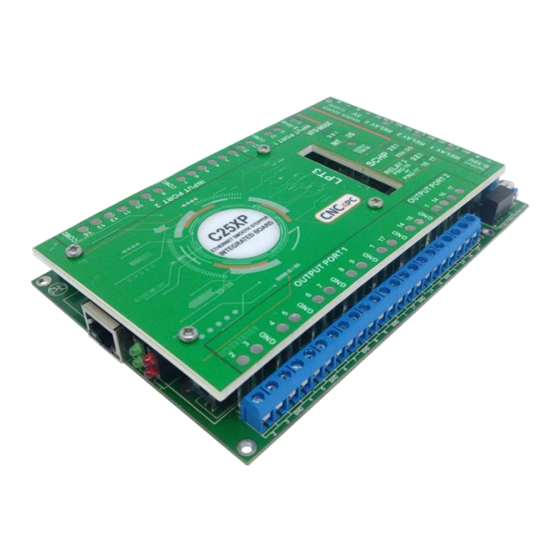
Page 5: Board Description
____________________________________________________________________________ BOARD DESCRIPTION ___________________________________________________________________________ User’s Manual Page 3... -
Page 6: Power Terminals And Configuration
____________________________________________________________________________ POWER TERMINALS AND CONFIGURATION Power terminal Regulated +10VDC or +30VDC is required to power this board. WARNING Check the polarity and voltage of the external power source and connect the 10VDC to 30VDC and GND. Overvoltage or reverse-polarity power applied to these terminals can cause damage to the board, and/or the power source Source Output 5VDC ___________________________________________________________________________... -
Page 7: Source Output 10-30Vdc
____________________________________________________________________________ Source Output 10-30VDC 10-30VDC can be sourced to sensors or other cards requiring PORT_3 ESS PORT_3 ESS Function OUTPUT IN/OUT IN/OUT IN/OUT IN/OUT IN/OUT IN/OUT IN/OUT IN/OUT P_10 INPUT P_11 INPUT P_12 INPUT P_13 INPUT P_14 OUTPUT P_15 INPUT P_16 OUTPUT P_17... -
Page 8: E-Stop Terminal
____________________________________________________________________________ E-STOP TERMINAL Connect an E-STOP push button as is shown in the below images. Pin 10 port 1 is used for E-Stop. Since this board controls the enable line, and the enable line is the one responsible for notifying the controller of the e-stop condition, the user does not have a direct access to the pin itself, just to the e-stop terminal on the board. -
Page 9: Configuration Jumper Mode Us Or Int
____________________________________________________________________________ Configuration jumper mode US or INT Configuration jumper pin 16 or 17 For the Variable speed control go to http://cnc4pc.com/Tech_Docs/VARIABLE_SPEED_CONTROL.pdf For Configure the control software go to http://cnc4pc.com/Tech_Docs/CONFIGURATION_OF_CONTROL_SOFWARE.pdf For Replacing Potentiometer go to http://cnc4pc.com/Tech_Docs/Replacing%20a%20Potentiometer.pdf ___________________________________________________________________________ User’s Manual Page 7... -
Page 10: Output Terminal For General Purpose
____________________________________________________________________________ OUTPUT TERMINAL FOR GENERAL PURPOSE Theses output are Open Collector In this terminal can be connected relay, led or lamps, alarm, etc. INDICATORS LEDs ___________________________________________________________________________ User’s Manual Page 8... -
Page 11: Wiring Sample Input Port_1 And Port_2
____________________________________________________________________________ 10.0 WIRING SAMPLE INPUT PORT_1 AND PORT_2 ___________________________________________________________________________ User’s Manual Page 9... -
Page 12: Wiring Sample Axi
____________________________________________________________________________ 11.0 WIRING SAMPLE AXI ___________________________________________________________________________ User’s Manual Page 10... -
Page 13: Wiring Sample Vfd
____________________________________________________________________________ 12.0 WIRING SAMPLE VFD ___________________________________________________________________________ User’s Manual Page 11... -
Page 14: Dimensions
____________________________________________________________________________ 13.0 DIMENSIONS All dimensions are in Millimeters. Disclaimer: Use caution. CNC machines can be dangerous machines. Neither DUNCAN USA, LLC nor Arturo Duncan are liable for any accidents resulting from the improper use of these devices. This product is not a fail-safe device and it should not be used in life support systems or in other devices where its failure or possible erratic operation could cause property damage, bodily injury or loss of life.
Need help?
Do you have a question about the C25XP and is the answer not in the manual?
Questions and answers