
Subscribe to Our Youtube Channel
Related Manuals for CNC4PC C82


Summary of Contents for CNC4PC C82
- Page 1 USER’S MANUAL VER.1 C82- MULTIFUNCTION CNC BOARD Rev. 3.2 MARCH 2020 ___________________________________________________________________________ User’s Manual Page i...
-
Page 2: Table Of Contents
USER'S MANUAL TABLE OF CONTENTS Contents Page # FEATURES ........................1 I/O SPECIFICATIONS ..................... 2 BOARD DESCRIPTION ....................2 POWER TERMINALS AND CONFIGURATION JUMPERS ..........3 Power terminal ......................3 Source Output 5VDC ....................3 Source Output 10-24VDC ..................3 Input terminals for port_1 and port_2 .............. -
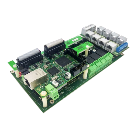
Page 3: Features
____________________________________________________________________________ FEATURES • Designed for ESS AND ETHER-MACH motion controller. • Built-in PWM-Based Speed Control and Two Built-in Electromechanical Relays with NO and NC positions for spindle control. • The system monitors: - E-Stop. - Safety Charge Pump. - VFD Fault. - Driver Fault. -
Page 4: I/O Specifications
____________________________________________________________________________ I/O SPECIFICATIONS OPTOISOLATED DIGITAL INPUT TTL SPECIFICATIONS On-state voltage range 5 to 24VDC Maximum off-state voltage 0.8V Typical signal delay 2.8uS DIGITAL OUTPUT TTL SPECIFICATIONS Maximum output voltage 5VDC Maximum output current 24mA Maximum off-state voltage 0.44 V Maximum supported frequency 400KHz Typical signal delay 10nS... -
Page 5: Power Terminals And Configuration Jumpers
____________________________________________________________________________ POWER TERMINALS AND CONFIGURATION JUMPERS Power terminal The board requires an external power supply which can deliver 10-24VDC@700mA to power the logic of the board and the ESS or ETHER-MACH, but keep in mind that each output can deliver up to 500mA and if powering other breakout or relays boards. So, you will need to add all the expected power consumption. -
Page 6: Input Terminals For Port_1 And Port_2
____________________________________________________________________________ Input terminals for port_1 and port_2 These terminals support signals 5-24VDC, you can connect sensors NPN, PNP, switches, capacitive sensors, etc. set jumpers depending on signal voltage. PORT_1 Jumper position change PORT_2 ___________________________________________________________________________ User’s Manual Page 4... -
Page 7: Select Jumper Com For The Inputs Of Port_1 And Port_2
____________________________________________________________________________ Select JUMPER COM for the inputs of port_1 and port_2 Set the Jumper to COM = +5VDC, GND or 10-24VDC to determine the common for the input signals to be used. COM = 5V PORT_2 PORT_1 COM = GND with 5VDC COM = GND with 10-24VDC COM = 10-24VDC ___________________________________________________________________________... -
Page 8: Jumper Position
____________________________________________________________________________ JUMPER POSITION Selecting the SCHP operation mode The Safety Charge Pump uses pin 17 on port 2. When the SCHP is enabled on the board, then the output of the terminals will be active while the Safety Charge Pump signal is present and inactive while the SCHP is not present. -
Page 9: Jumper Configuration Driver Enable
____________________________________________________________________________ Jumper configuration driver enable 1-2: Driver enable ON 2-3: Driver enable OFF Jumper configuration driver fault 1-2: Driver fault ON 2-3: Driver fault OFF Configuration jumper pin 16 or 17 1-2: PIN17 2-3: PIN16 ___________________________________________________________________________ User’s Manual Page 7... -
Page 10: Connection Example For Shield C78
____________________________________________________________________________ CONNECTION EXAMPLE FOR SHIELD C78 RJ45 shield C78 connection for axes, Limits and Encoder RJ45 shield board description ___________________________________________________________________________ User’s Manual Page 8... -
Page 11: Pinout
____________________________________________________________________________ Pinout RJ45_7 RJ45_8 RJ45_9 RJ45_10 RJ45 PIN P.P. PIN RJ45 PIN P.P. PIN RJ45 PIN P.P. PIN RJ45 PIN P.P. PIN 5VDC 1_13 2_17 1_12 2_16 2_4(INDEX) 1_11 2_11 1_15 1_15 2_14 2_2(enc. A) 2_11 12/24VDC 12/24VDC 5VDC 2_3(enc. B) 12/24VDC ___________________________________________________________________________ User’s Manual... -
Page 12: Connection Example For Shield C77
____________________________________________________________________________ CONNECTION EXAMPLE FOR SHIELD C77 Terminal Shield Screw-on Shield board description ___________________________________________________________________________ User’s Manual Page 10... -
Page 13: Driver Disconnection Jumpers
____________________________________________________________________________ DRIVER DISCONNECTION JUMPERS Nota: 1-2: Cable disconnection detection. 2-3: No cable disconnection detection. This configures how cable disconnect is to work. Set according to C34 board manual. E-STOP TERMINAL Connect an E-STOP push button as is shown in the below images. Pin 10 port 1 is used for E-Stop. -
Page 14: Typical Connections
____________________________________________________________________________ TYPICAL CONNECTIONS -Wiring inputs using an external 10-30VDC power supply to keep input circuit isolated. -Wiring inputs using an external 5VDC power supply to keep input circuit isolated. ___________________________________________________________________________ User’s Manual Page 12... -
Page 15: Led Indicator
____________________________________________________________________________ LED INDICATOR The standby LED lights indicate that the system is ready but disabled. When Status LED, (Green LED) lights, it indicates that the system is enabled. There are 4 possible error sources: a driver fault, E-STOP error, SCHP error or VFD alarm. - Page 16 ____________________________________________________________________________ For the Variable speed control go to http://cnc4pc.com/Tech_Docs/VARIABLE_SPEED_CONTROL.pdf For Configure the control software go to http://cnc4pc.com/Tech_Docs/CONFIGURATION_OF_CONTROL_SOFWARE.pdf For Replacing Potentiometer go to http://cnc4pc.com/Tech_Docs/Replacing%20a%20Potentiometer.pdf ESS MOTHER BOARD https://cnc4pc.com/ethernet-smooth-stepper-board.html ___________________________________________________________________________ User’s Manual Page 14...
-
Page 17: Dimensions
____________________________________________________________________________ DIMENSIONS All dimensions are in Millimeters. Fixing holes (4mm). Disclaimer: Use caution. CNC machines can be dangerous machines. Neither DUNCAN USA, LLC nor Arturo Duncan are liable for any accidents resulting from the improper use of these devices. This product is not a fail-safe device and it should not be used in life support systems or in other devices where its failure or possible erratic operation could cause property damage, bodily injury or loss of life.
Need help?
Do you have a question about the C82 and is the answer not in the manual?
Questions and answers