
Related Manuals for Teknim TWM-3885


Summary of Contents for Teknim TWM-3885
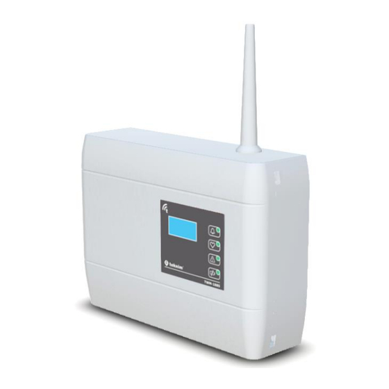
- Page 1 TWM-3885 Conventional Wireless Coordinator Installation & User Manual Release Date: 15/09/2021 Rev:01...
-
Page 2: Table Of Contents
TWM-3885 CONVENTIONAL WIRELESS COORDINATOR – R01 Contents General Definitions .......................... 2 Technical Specifications ........................2 Installation ............................3 Mounting ..........................3 3.1.1 Cable Holes ........................4 3.1.2 Wall Mounting ......................... 4 Antenna Installation ........................ 4 Supply Connection ........................6 Zone Alarm Resistor Connection ..................... 6 Zone Line Connection ...................... -
Page 3: General Definitions
(1) TLPWAN (Teknim Low Power Wide Area Network) is a wireless communication protocol developed by Teknim which allows low power consumption devices on a wider area in a stable and safe manner by using two-way communication. -
Page 4: Installation
TWM-3885 CONVENTIONAL WIRELESS COORDINATOR – R01 Installation Under this topic, the installation of TWM-3885 Conventional Wireless Coordinator module will be explained step by step in details. Please read all steps carefully. Mounting The following articles must be followed carefully in order to provide a good communication with the devices connected to the coordinator: •... -
Page 5: Cable Holes
Figure 1 – Mounting Hole Sizes Antenna Installation TWM-3885 Conventional Wireless Coordinator module is placed in the box with the antenna wire and antenna housing disassembled. Ensure a good installation of the antenna in order to provide a good TWM-3885 CONVENTIONAL WIRELESS COORDINATOR – R01... - Page 6 TWM-3885 CONVENTIONAL WIRELESS COORDINATOR – R01 communication between devices. Otherwise, there may be distance problems and communication performance losses. There are two superposed cards connected to each other in the module: The upper one of those is TLPWAN-RF card, while the other serves as the Flashlink interface and control card. The antenna terminal is located on the TLPWAN-RF positioned as the lower card.
-
Page 7: Supply Connection
TWM-3885 CONVENTIONAL WIRELESS COORDINATOR – R01 Şekil 3 - Anten Muhafazası Montajı Supply Connection Pass the cables from cable holes and strip their ends at a proper length, then make the supply connections as shown in the following connection diagram. Make sure that the terminal screws are tightened firmly. -
Page 8: Zone Line Connection
The value of alarm resistor must have been indicated in the user manual of your fire alarm panel. Teknim conventional fire alarm panels use “470R” resistors as alarm resistors. -
Page 9: Siren Line Connection
TWM-3885 CONVENTIONAL WIRELESS COORDINATOR – R01 Line end resistance (Teknim: 4K7) Z-OUT Z+IN Conventional Z-IN Fire Panel Figure 6 - Coordinator Zone Connection Diagram 1 In cases where the coordinator is connected to the end of the zone line, the line end resistance gets directly connected to the necessary terminals as shown in the following connection diagram. - Page 10 TWM-3885 CONVENTIONAL WIRELESS COORDINATOR – R01 connection methods for connecting the conventional wireless coordinator to the conventional siren line. In case where the coordinator is connected to the middle of the siren line, the line end resistance connects to another siren at the end of the line. The coordinator provides the siren line to be completed by connecting “SIREN-IN”...
-
Page 11: Module Interface
TWM-3885 CONVENTIONAL WIRELESS COORDINATOR – R01 Line end resistance (Teknim: 4K7) SIREN-OUT SIREN+ SIREN+IN Conventional SIREN- SIREN-IN Fire Panel Figure 9 - Coordinator Siren Connection Diagram 2 Module Interface Tamper Button Supply OLED Screen L3 - Alarm Led Alarm Resistor L4 –... -
Page 12: Programming Menu
TWM-3885 CONVENTIONAL WIRELESS COORDINATOR – R01 Besides, it checks whether the reset button on the panel is pushed or not by monitoring the voltage on the zone line. • Siren Connection: The coordinator makes the fire alarm panel give a siren open circuit fault by connecting or disconnecting the line end resistance to the line through the siren connection. -
Page 13: Settings
TWM-3885 CONVENTIONAL WIRELESS COORDINATOR – R01 Events To enter the menu: “Main Screen” > FORWARD > “Events” > FORWARD Events >1.Alarm 2.Fault 3.Warning Any category can be selected from the “Events” screen shown above, and the devices under the selected category are listed. Example: “Fault” category is selected in the following figure and the devices in fault state are listed. - Page 14 TWM-3885 CONVENTIONAL WIRELESS COORDINATOR – R01 Settings To enter the menu: “Main screen” > FORWARD > DOWN > “Settings” > FORWARD Settings >1.Channel 2.Language 3.Contrast 3.8.2.1 Channel Each small frequency range obtained by dividing the frequency range reserved for TLPWAN into 10 segments, corresponds to one channel.
-
Page 15: Functions
TWM-3885 CONVENTIONAL WIRELESS COORDINATOR – R01 To change the language, navigate through the language options by using UP and DOWN buttons. Press FORWARD button to approve and see the “Successful” inscription on the screen. Press BACK button to exit from the menu or to cancel the changed value. - Page 16 TWM-3885 CONVENTIONAL WIRELESS COORDINATOR – R01 A wireless system (PAN) is initially needed for the wireless devices to be connected to a network. If there is a network set, the “Heart Led” blinks. If no network is set, the “Heart Led” is off. Thus, the “Heart Led”...
- Page 17 TWM-3885 CONVENTIONAL WIRELESS COORDINATOR – R01 Permission” menu. To enter the connection permission screen, navigate through the functions menu by using UP and DOWN buttons and select “Connection Permission” menu. Increase or decrease the value by using UP and DOWN buttons for changing the connection permission.
-
Page 18: Device List
TWM-3885 CONVENTIONAL WIRELESS COORDINATOR – R01 3.8.4 Device List The list of the devices connected to the wireless network can be accessed from this menu. Address values, RSSI value, battery status, number of successful and unsuccessful data transmissions and device deletion operations are carried out on the “Device Detail”... -
Page 19: Information
TWM-3885 CONVENTIONAL WIRELESS COORDINATOR – R01 is observed. Device battery is taken out and installed back again after a while for resetting the PER value or it can be reset by using the “Reset PER” option from the device menu. If the PER value still continues to increase the RF intensity in the environment must be checked. -
Page 20: Ping Time
TWM-3885 CONVENTIONAL WIRELESS COORDINATOR – R01 6. Indicated the channel on which the PAN is set. 7. Each PAN has its own PAN ID. This value is selected randomly during the PAN setup operation between “1-65535” as a unique number. If more than one PAN is required to be set on the same channel, the PAN ID provides the data traffic between the PANs run uninterruptedly. -
Page 21: Quick Menu Access
TWM-3885 CONVENTIONAL WIRELESS COORDINATOR – R01 Quick Menu Access General structure of the module menu is shown in the following diagram. Address Device X Fire Type Fires Device Z Address Events Fault 1 Faults Device A Fault 2 Warnings Fault.. -
Page 22: Events And Indicators
TWM-3885 CONVENTIONAL WIRELESS COORDINATOR – R01 Events and Indicators The events about all devices on the wireless system and the manner of displaying such events are shown in the following tables. Wireless Detector OLED Smoke Alarm Temperature Alarm Pollution Alarm... -
Page 23: Signal Strength Table (Rssi Table)
TWM-3885 CONVENTIONAL WIRELESS COORDINATOR – R01 Signal Strength Table (RSSI Table) RSSI is an abbreviation being used in RF terminology. It stands for Received Signal Strength Indicator. It is a measurement value of the current strength of the radio signals received by the device. This value is directly related to the distance between the receiver and the transmitter and also to the other environmental factors. -
Page 24: Software Update
TWM-3885 CONVENTIONAL WIRELESS COORDINATOR – R01 Software Update You may download the software files of all wireless devices under the “Firmware & Software” section of www.teknim.com.tr web site and carry out the update operation by using “Teknim Updater” software. 1922 Bilgi Elektronik San.
Need help?
Do you have a question about the TWM-3885 and is the answer not in the manual?
Questions and answers