Table of Contents
Advertisement
Available languages
Available languages
Quick Links
Advertisement
Chapters
Table of Contents

Subscribe to Our Youtube Channel
Related Manuals for Uniks GHOST METER F


Summary of Contents for Uniks GHOST METER F
- Page 1 Ghost meter Manuale d’uso User manual ITALIANO: Si prega di leggere questo manuale prima di accendere l'apparecchio. Informazioni importanti sulla sicurezza interna ENGLISH: Please read this manual before turning on the appliance. Important information on internal security...
- Page 2 GHOST METER F...
- Page 3 GHOST METER F REGISTRA IL TUO PRODOTO SU www.uniks.it La registrazione dei tuoi prodotti ti permetterà di rimanere sempre informato sulle novità, usufruire di vantaggiosi sconti dedicati a te per l'acquisto di accessori e prodotti per il tuo lavoro quotidiano.
-
Page 4: Table Of Contents
GHOST METER F Sommario INTRODUZIONE ................6 Caratteristiche principali: ..............6 SICUREZZA ..................7 3.1. SIMBOLI INTERNAZIONALI DI SICUREZZA ........7 3.2. INSTALLAZIONE SOVRATENSIONE PER IEC1010 CATEGORIA SOVRATENSIONE ..................7 3.3. ISTRUZIONI DI SICUREZZA ..............8 DESCRIZIONE ................. 9 4.1. - Page 5 GHOST METER F TERMOGRAFIA E FUNZIONAMENTO DEL MULTIMETRO ..20 6.1. Nozioni base sulla termocamera ............20 6.2. Uso del termocamera ................22 6.3. Uso del multimetro con termocamera ..........23 6.3.1. Memorizzazione immagini termografiche ......... 23 6.3.2. Acquisizione dei valori MAXMIN in modalità IR+DMM ..... 23 6.3.3.
-
Page 6: Introduzione
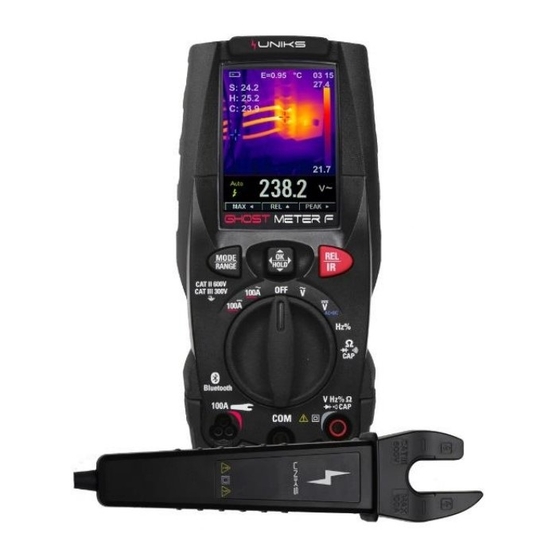
INTRODUZIONE Multimetro digitale in vero valore efficace con termocamera integrata e display LCD TFT a colori, convertitore A/D ad alta frequenza. Il Ghost Meter F è dotato di memoria interna e Bluetooth per inviare le immagini termografiche nell’ APP IR GHOST. -
Page 7: Sicurezza
GHOST METER F SICUREZZA 3.1. SIMBOLI INTERNAZIONALI DI SICUREZZA ATTENZIONE – attenersi alle istruzioni riportate nel manuale; un uso improprio potrebbe causare danni allo strumento o ai suoi componenti. Questo simbolo WARNING indica una situazione potenzialmente pericolosa, che, se non evitato, potrebbe provocare la morte o... -
Page 8: Istruzioni Di Sicurezza
GHOST METER F apparecchiature, per esempio i motori fissi con collegamento ad impianto fisso CATEGORIA SOVRATENSIONE IV Le apparecchiature della CATEGORIA SOVRATENSIONE IV servono per effettuare le misure su una sorgente di un’installazione a bassa tensione. Esempi sono costituiti da contatori elettrici e da misure sui dispositivi primari di protezione dalle sovracorrenti e sulle unità... -
Page 9: Descrizione
GHOST METER F DESCRIZIONE 4.1. DESCRIZIONE ANTERIORE E POSTERIORE 1. display LCD 9. Lente termocamera 2. Pulsante MODE/RANGE 10. Selettore per aprire il coperchio di 3.Pulsante navigazione menu protezione della lente 4. Pulsante modalità termica / REL 11 Apertura 5. Selettore funzioni 12. -
Page 10: Descrizione I Pulsanti
GHOST METER F 4.2. DESCRIZIONE I PULSANTI I 9 pulsanti sulla parte anteriore del multimetro attivano le funzioni che aumentano la funzione selezionata, usando la manopola per navigare nei menu o controllare l'alimentazione dei circuiti del multimetro. 4.2.1. Cursori selezionare una voce di un menu, regolare il contrasto del display, scorrere le informazioni, ed eseguire l'immissione dei dati. -
Page 11: Descrizione Del Display
GHOST METER F 4.3. DESCRIZIONE DEL DISPLAY 4.3.1. Misure sul display LCD 1. Livello di carica della batteria 9. Unità di misura temperatura 2. Orario 10. Temperatura rilevata 3. Funzione Attiva 11 Croce a punto centrale 4. Unità di misura 12. -
Page 12: Descrizione Selettore Rotativo
GHOST METER F 4.4. DESCRIZIONE SELETTORE ROTATIVO • Selezionare una funzione di misura primaria posizionando il selettore rotante su una delle icone lungo il suo perimetro. • Per ogni funzione, il multimetro presenta il display standard per quella funzione (Range, Unità di misura). -
Page 13: Misura Di Tensione Ac+Dc
GHOST METER F 5.2. Misura di tensione AC+DC ATTENZIONE: Non misurare le tensioni DC se un motore sul circuito viene acceso o spento, Grandi picchi di tensione possono verificarsi che possono danneggiare il misuratore. 1. Impostare il commutatore di funzione sulla posizione VDC. -
Page 14: Misura Di Frequenza
GHOST METER F 1. Impostare il commutatore di funzione sulla posizione VDC. 2. Inserire lo spinotto a banana del puntale di test nero nella presa COM negativa. 3. Inserire lo spinotto a banana del puntale di test rosso nella presa V positivo. -
Page 15: Misura Della Resistenza
GHOST METER F 5.5. Misura della resistenza ATTENZIONE: Per evitare scosse elettriche, scollegare l'alimentazione all'unità in prova e scaricare tutti i condensatori prima di effettuare eventuali misurazioni di resistenza, rimuovere le batterie e scollegare i cavi di linea. 1. Impostare l'interruttore di funzione sulla posizione Ω. -
Page 16: Test Del Diodo
GHOST METER F 5.7. Test del Diodo 1. Impostare il commutatore di funzione sulla posizione 2. Inserire lo spinotto a banana del puntale da test nero nella Presa negativa COM. 3. Inserire lo spinotto a banana del puntale da test rosso nella presa positiva 4. -
Page 17: Misura Corrente Dc Con Pinza A Forcella
GHOST METER F 5.9. Misura corrente DC con Pinza a Forcella 1. Impostare il selettore sulla posizione 100A DC. 2. Inserire la spina della sonda della pinza a forcella nel jack valido. 3. Leggere i dati correnti sul display. 5.10. Misura corrente AC con Pinza a Forcella 1. -
Page 18: Range
GHOST METER F 5.11. Range • Premere il tasto RANGE per attivare la modalità manuale e per disattivare la funzione Autorange. • Nella parte superiore sinistra del display appare il messaggio "Manual Range" invece di "Auto Range". • In modalità manuale, premere il tasto RANGE per modificare il campo di misura: il relativo punto decimale cambierà... -
Page 19: Acquisizione Dei Valori Minimi E Massimi
GHOST METER F 5.13. Acquisizione dei valori minimi e massimi • La modalità MAX MIN acquisisce i valori di ingresso minimo e massimo. • Quando l'ingresso va al di sotto del valore minimo registrato o al di sopra del valore massimo registrato, lo strumento emette un segnale acustico e registra il nuovo valore. -
Page 20: Catturare I Valori Di Picco (Peak)
GHOST METER F 5.15. Catturare i valori di picco (PEAK) • Per attivare la modalità di picco, premere il contrassegnato con " ". • Se lo strumento è già in funzione di picco (PEACK), premere " " per disattivare la modalità Picco (PEAK). - Page 21 GHOST METER F 1 L'indicatore della capacità della batteria. 2 Valore di Emissività attualmente selezionato. Utilizzare il menu Thermal Settings (Impostazioni termiche) per modificare il valore di emissività. 3 Icona dell'unità di misura della temperatura, Utilizzare il menu Thermal Settings (Impostazioni termiche) per selezionare "°C,°F,K".
-
Page 22: Uso Del Termocamera
GHOST METER F 6.2. Uso del termocamera Per il funzionamento di base seguire questi passi: 1. Impostare l'interruttore di funzione su una posizione qualsiasi. 2. Premere il pulsante "IR" per accendere alla FUNZIONE TERMOCAMERA (assicurarsi di aver aperto il copri lente nel retro) 3. -
Page 23: Uso Del Multimetro Con Termocamera
GHOST METER F pixel del rivelatore sono 34um; FOV orizzontale è 21°, FOV verticale è 21°, IFOV è 34um/7.5mm = 4.53mrad; D:S teorico (=1/ IFOV teorico) = 220:1 • La misura D:S (=1/ IFOVmeasure) è la dimensione del punto necessaria per fornire una misura accurata della temperatura. -
Page 24: Acquisizione Dei Valori Di Picco In Modalità Ir+Dmm
GHOST METER F e visualizzare il valore max. 2. Se il misuratore è già in funzione MAX/MIN, premere il tasto " " per visualizzare il valore min, poi premere il tasto " " per visualizzare il valore di misura attuale, premere di nuovo il tasto per visualizzare il valore massimo. -
Page 25: Impostazioni Del Menu
GHOST METER F IMPOSTAZIONI DEL MENU 7.1. Utilizzo dei menu di impostazione Premere il pulsante MENU per aprire i menu di impostazione, come mostrato di seguito... -
Page 26: Impostazioni Dettagli
GHOST METER F • Premere i pulsanti SU/GIÙ per selezionare la voce di menu o modificare il valore della voce di messa a fuoco corrente. • Premere il tasto RIGHT/MENU per entrare nel sottomenu o impostare la messa a fuoco della voce di menu correntemente selezionata. -
Page 27: Unità Di Misura Temperatura
GHOST METER F 7.2.2. Unità di misura temperatura • Premere il pulsante RIGHT/MENU per impostare la messa a fuoco di questa opzione e il colore del valore dell'opzione cambierà in nero °C. • Stato di messa a fuoco, utilizzare il pulsante DESTRA/MENU per attivare °C, °F e K, utilizzare il pulsante LEFT/ RIGHT/MENU per uscire dalla messa a fuoco e il colore del valore dell'opzione cambierà... -
Page 28: Emissività
GHOST METER F 7.2.4. Emissività • Premere il pulsante RIGHT/MENU per impostare la messa a fuoco di questa opzione. • Nello stato di messa a fuoco, usare il tasto SU/GIÙ per aumentare o diminuire il valore dell'emissività, usare il tasto LEFT/ RIGHT/MENU per uscire dallo stato di messa a fuoco. -
Page 29: Setup
GHOST METER F 7.2.6. Setup • Premere il pulsante RIGHT/MENU per accedere al menu. Sono disponibili cinque opzioni: Suono tasti, Luminosità e Spegnimento automatico. • Suono chiave: utilizzare il pulsante DESTRA / MENU per attivare o disattivare il segnale acustico. -
Page 30: Data E Ora
GHOST METER F 7.2.7. Data e Ora • Premere il pulsante RIGHT/MENU per accedere al menu . • In questo menu è possibile impostare anno, mese, giorno, minuti e ora. • Le modifiche diventano effettive dopo essere usciti dai menu delle... -
Page 31: Informazioni Di Sistema
GHOST METER F 7.2.8. Informazioni di Sistema • Premere il pulsante RIGHT/MENU per accedere al menu. • Questo menu contiene la versione del software, la versione dell'hardware e la versione della termocamera. Resetta alla configurazione iniziale di fabbrica 7.2.9. • Quando si seleziona l'opzione Impostazioni di fabbrica, dopo aver premuto il pulsante RIGHT/MENU, la finestra di dialogo verrà... -
Page 32: Manutenzione
GHOST METER F MANUTENZIONE ATTENZIONE • Solo i tecnici esperti devono eseguire le operazioni di manutenzione; prima di eseguire la manutenzione scollegare tutti i cavi dai terminali di ingresso. • Non utilizzare lo strumento in ambienti con elevati livelli di umidità o alte temperature, non esporre a luce diretta. -
Page 33: Pulizia Dello Strumento
GHOST METER F Posizionare il selettore su OFF e rimuovere i cavi dai terminali di ingresso. Aprire Blocco coperchio interfaccia USB, inserire l'interfaccia dell'alimentatore del caricabatterie nell'interfaccia USB. Un simbolo lampeggiante indica una batteria verde sul display. Il processo di ricarica è completo quando il simbolo è costante. -
Page 34: Specifiche Tecniche
GHOST METER F SPECIFICHE TECNICHE 9.1. Caratteristiche tecniche 9.1.1. Termocamera Campo visivo (FOV) / Distanza minima di messa a fuoco: 21°x21°/ 0.5m Risoluzione spaziale (IFOV) 4.53mrad Risoluzione IR 80 x 80 Pixels Sensibilità termica / NETD <0.1°C a 30°C (86°F) / 100 mK... - Page 35 GHOST METER F Funzione Range Risoluzione Precisione 4.000V 0.001V 50Hz-60Hz: ±(1.0% + 5 digits) Tensione AC 61Hz-1kHz: ±(2.5% + 5 digits)) TRMS 40.00V 0.01V 400.0V 0.1V 600V Precisione specificata dal 10% al 100% del campo di misura, onda sinusoidale; Impedenza di ingresso:> 9 MΩ; Precisione funzione PEAK: ± 10% rdg; Tempo di risposta PEAK: 1ms.
- Page 36 GHOST METER F Funzione Range Risoluzione Precisione ±(10% + 10 digits) Test di Resistenza e 400.0 0.1 continuità ±(1.0% + 5 digits) 4.000k 0.001k 40.00k 0.01k 400.0k 0.1k 4.000M 0.001M ±(2.5% + 10 40.00M 0.01M digits) Buzzer:> 50Ω; Protezione da sovraccarico: 600VDC / ACrms.
- Page 37 GHOST METER F Range di frequenza degli impulsi: 40Hz-10kHz; Ampiezza dell'impulso: ± 5 V (100us-100ms). Funzione Range Risoluzione Precisione 40.00nF 0.01nF ±(3.0% + 20 Capacità digits) 400.0nF 0.1nF ±(3.0% + 8 digits) 4.000µF 0.001µF 40.00µF 0.01µF 400.0µF 0.1µF 4000µF 1µF ±(3.5% + 20...
-
Page 38: Specifiche Generali
GHOST METER F 9.1.3. Specifiche Generali Standard di riferimento IEC / EN 61010-1 Sicurezza IEC / EN 61326-1 Doppio isolamento Isolamento Livello di inquinamento CAT III 600V, CAT IV 300V Categoria di sovratensione 2000m (6562ft) Altitudine operativa massima Alimentazione elettrica... -
Page 39: Assistenza
GHOST METER F 10. ASSISTENZA 10.1. Condizioni di Garanzia Questo strumento è garantito contro ogni difetto di materiale e fabbricazione, in conformità con le condizioni generali di vendita. Durante il periodo di garanzia, le parti difettose possono essere sostituite, ma il costruttore si riserva il diritto di riparare ovvero sostituire il prodotto. -
Page 40: Assistenza
GHOST METER F 10.2. Assistenza Se lo strumento non funziona correttamente, prima di contattare il Servizio di Assistenza, controllare lo stato di usura della batteria e dei cavi e sostituirli ove necessario. Se lo strumento continua a manifestare malfunzionamenti controllare se la procedura di utilizzo dello stesso è conforme a quanto indicato nel presente manuale. - Page 41 Summary INTRODUCTION ................43 Key Features: ................. 43 SAFETY ..................44 3.1. Safety Infomation ................44 3.2. PER IEC1010 OVERVOLTAGE INSTALLATION CATEGORY ..44 3.3. Safety Instructions ................45 DESCRIPTION ................46 4.1. Meter Description ................46 4.2. Understanding the Push Buttons ............47 4.2.1.
- Page 42 GHOST METER F THERMAL IMAGER AND DMM OPERTION ......... 57 6.1. Thermal Imager Basics ............... 57 6.2. Using the Thermal Imager ..............59 6.3. Using the Multimeter with Thermal Imager ......... 60 6.3.1. Memory and APP ................60 6.3.2. Capturing MAXMIN Values on IR+DMM Mode ......61 6.3.3.
-
Page 43: Introduction
GHOST METER F INTRODUCTION • Professional True RMS Industrial Digital Multimeter with built-in Thermal Imager, and TFT color LCD display, providing fast A/D converting sampling time, high accuracy. • It is easy to find and solve the problems of the production equipments, providing Bluetooth technology. -
Page 44: Safety
GHOST METER F SAFETY 3.1. Safety Infomation This symbol adjacent to another symbol, terminal or operating device indicates that the operator must refer to an explanation in the Operating Instructions to avoid personal injury or damage to the meter. This WARNING symbol indicates a potentially hazardous situation, which if not avoided, couldresult in death or serious injury. -
Page 45: Safety Instructions
GHOST METER F OVERVOLTAGE CATEGORY IV Equipment of OVERVOLTAGE CATEGORY IV is for use at the origin of the installation. Note: Examples include electricity meters and primary over-current protection equipment. 3.3. Safety Instructions • This meter has been designed for safe use, but must be operated with caution. -
Page 46: Description
GHOST METER F DESCRIPTION 4.1. Meter Description 1. LCD Display 9. Thermal Imager Len 2. MODE/RANGE Button 10. Len Cover 3. Navigation/Menu Button 11 Probe Slot 4. Thermal Mode/REL Button 12. Support Plate 5. Rotary Function Switch 13. Work Light 6 Positive (+) Probe Input Jack for Fork Clamp Current 14. -
Page 47: Understanding The Push Buttons
GHOST METER F 4.2. Understanding the Push Buttons The 9 push buttons on the front of the Meter activate features that augment the function selected using the rotary switch, navigate menus or control power to Meter circuits. 4.2.1. Cursor Buttons Select an item in a menu, adjust display contrast, scroll through information, and perform data entry. -
Page 48: Understanding The Display
GHOST METER F 4.3. Understanding the Display 4.3.1. Measurement on LCD Dispaly 1-Battery Charge Level 9-Temperature Unit 2-System’s Time 10-Temperature Readings 3-Function Keys 11-Centre Point Cross 4-Measuring Unit 12-Cold Point Cross 5-Measuring Result 13-Hot Point Cross 7-Analogue Bargraph 14-Color Bar... -
Page 49: Understanding The Rotary Switch
GHOST METER F 4.4. Understanding the Rotary Switch • Select a primary measurement function by positioning the rotary switch to one of the icons around its perimeter. • For each function, the Meter presents a standard display for that function (Range, Measurement Units and Modifiers). -
Page 50: Dmm Measurement And Setup
GHOST METER F DMM MEASUREMENT AND SETUP 5.1. DC Voltage Measurement CAUTION: Do not measure DC voltages if a motor on the circuit is being switched ON or OFF, Large voltage surges may occur that can damage the meter 1. Set the function switch to the VDC position. -
Page 51: Ac Voltage Measurement
GHOST METER F 5.3. AC Voltage Measurement WARNING: Risk of Electrocution. The probe tips may not be long enough to contact the live parts inside some 240V outlets for appliances because the contacts are recessed deep in the outlets. As a result, the reading may show 0 volts when the outlet actually has voltage on it. -
Page 52: Resistance Measurement
GHOST METER F 5.5. Resistance Measurement WARNING: To avoid electric shock, disconnect power to the unit under test and discharge all capacitors before taking any resistance measurements, Remove the batteries and unplug the line cords. 1. Set the function switch to the Ω... -
Page 53: Diode Test
GHOST METER F 5.7. Diode Test 1. Set the function switch to the position. 2. Insert the black test lead banana plug into the negative COM jack. 3. Insert the red test lead banana plug into the positive jack. 4. Press the MODE/RANGE Button to switch the Diode functions. -
Page 54: Fork Clamp Dc Current Measurement
GHOST METER F 5.9. Fork Clamp DC Current Measurement 1. Set the function switch to the 100A DC position. 2. Insert Fork clamp probe plug into the valid jack. 3. Read the current data in the display. 5.10. Fork Clamp AC Current Measurement 1. -
Page 55: Using Range
GHOST METER F 5.11. Using RANGE • Press the RANGE key to activate the manual mode and to disable the Autorange function. • The message “Manual Range” appears on the upper left part of the display instead of “Auto Range”. -
Page 56: Capturing Minimum And Maximum Values
GHOST METER F 5.13. Capturing Minimum and Maximum Values • The MAX MIN Record mode captures minimum and maximum input values. • When the input goes below the recorded minimum value or above the recorded maximum value, the meter beeps and records the new value. -
Page 57: Capturing Peak Values
GHOST METER F 5.15. Capturing Peak Values • To activate the peak mode, press the soft key labeled “ ”. • If the meter is already in the peak function, “ ” causes the meter to turn off peak. THERMAL IMAGER AND DMM OPERTION 6.1. - Page 58 GHOST METER F 1-The Battery capacity indicator. 2-The currently selected Emissivity value. Use the Thermal Settings Menu to change the emissivity value. 3-The temperature unit icon, Use the Thermal Settings Menu to select “°C,°F,K”. 4-Current time Display 5-Center cross of the thermal imager temperature measurement, represents the centre spot temperature of the scene.
-
Page 59: Using The Thermal Imager
GHOST METER F color, the warmer the temperature; The darker the color, the cooler the temperature. 17-Highest reading measured in the current frame. 6.2. Using the Thermal Imager For basic operation follow these steps: 1. Set the function switch to any position. -
Page 60: Using The Multimeter With Thermal Imager
GHOST METER F D:S theoretical (=1/ IFOV theoretical) = 220:1 • D:S measure (=1/ IFOV measure) is the spot size needed to provide an accurate temperature measure. • Typically D:S measure is 2 to 3 times smaller than D:S theoretical, which means the temperature measurement area of the target need to be 2 to 3 times larger than that determined by the calculated theoretical D:S. -
Page 61: Capturing Maxmin Values On Ir+Dmm Mode
GHOST METER F 6.3.2. Capturing MAXMIN Values on IR+DMM Mode 1. To activate the maxmin mode, press the softkey labeled “ ”, and display max value. 2. If the Meter is already in the maxmin function, then Press the “ ” key to display min value, then Press the “... -
Page 62: Capturing Peak Values On Ir+Dmm Mode
GHOST METER F 6.3.3. Capturing Peak Values on IR+DMM Mode 1. To activate the peak mode, press the softkey labelled “ ”, and display Peak max value. 2. If the Meter is already in the peak function, then Press the “ ” key to display Peak min value, then Press the “... -
Page 63: Settings Menus
GHOST METER F SETTINGS MENUS 7.1. Using Settings Menus • Press MENU Button to open the Settings Menus, as show below. • Press UP/DOWN Button to select menu item or change the value of current focus item. • Press RIGHT/MENU Button to enter the submenu or set focus on the current selected item. -
Page 64: Settings Details
GHOST METER F 7.2. Settings Details 7.2.1. Palette Mode • Thermal imager has five kinds of palette, such as: • Press RIGHT/MENU Button to select one of the display color palettes 7.2.2. Temp Unit • Press RIGHT/MENU Button to set focus on this option and the color of option value will change to black °C. -
Page 65: Measure
GHOST METER F 7.2.3. Measure • Press RIGHT/MENU Button to enter measure menu. • Two selections are available: Temp. Max and Temp. Min. • Press RIGHT/MENU Button to set cur select item on or off. • Hot Point: This option enables thermal imager automatically detect the highest temperature point. -
Page 66: Language
GHOST METER F 7.2.5. Language • Press RIGHT/MENU Button to enter language menu. • Three options are available: Simplified Chinese, Traditional Chinese and English. • Use UP/DOWN Button to select language and use RIGHT/MENU button to set selected language to be valid... -
Page 67: Common
GHOST METER F 7.2.6. Common • Press RIGHT/MENU Button to enter common menu, Five options are available: Key sound, Brightness and Auto Off. • Key Sound: Use RIGHT/MENU Button to set beep on or off. • Brightness: Press RIGHT/MENU Button to set focus on this option. In focus state, use UP/DOWN button to change LCD’s brightness, use... -
Page 68: Sys Info
GHOST METER F 7.2.8. Sys Info • Press RIGHT/MENU Button to enter system infomation menu. • This menu contains software’s version, hardware’s version and thermal imager’s version. -
Page 69: Factory Set
GHOST METER F 7.2.9. Factory Set • When select Factory Set option, after press RIGHT/MENU Button, thedialog box will be displayed as show below. • Select “YES” Button, system parameter will be reset. MAINTENANCE CAUTION • Only expert and trained technicians should perform maintenance operations, Before carrying out maintenance operations, disconnect all cables from the input terminals. - Page 70 GHOST METER F 8.1. Recharging the Internal Battery When the LCD displays symbol “ ”, it is necessary to recharge the internal battery. Recharging the Internal Battery 1.Position the rotary switch to OFF and remove the cables from the input terminals.
-
Page 71: Cleaning The Instrument
GHOST METER F Warming Open USB Interface Cover Lock 8.2. Cleaning the Instrument Use a soft and dry cloth to clean the instrument, Never use wet cloths, solvents, water, et. 8.3. Fine vita WARNING: The symbol on the instrument indicates that the appliance... -
Page 72: Technical Specifications
GHOST METER F TECHNICAL SPECIFICATIONS 9.1. Technical Characteristics 9.1.1. Thermal Imager Field of View (FOV) / Minimum Focus Distance : 21°x21°/ 0.5m Spatial Resolution (IFOV) 4.53mrad IR Resolution 80 x 80 Pixels Thermal sensitivity/NETD <0.1°C at 30°C (86°F) / 100 mK... - Page 73 GHOST METER F Function Range Resolution Accuracy 4.000V 0.001V 50Hz-60Hz: ±(1.0% + 5 digits) AC TRMS 61Hz-1kHz: ±(2.5% + 5 digits)) Voltage 40.00V 0.01V 400.0V 0.1V 600V Accuracy specified from 10% to 100% of the measuring range, sine wave; Input Impedance: >9MΩ; Accuracy PEAK function: ±10%rdg; PEAK response time: 1ms.
- Page 74 GHOST METER F Function Range Resolution Accuracy ±(10% + 10 digits) Resistance and 400.0 0.1 Continuity ±(1.0% + 5 digits) 4.000k 0.001k Test 40.00k 0.01k 400.0k 0.1k 4.000M 0.001M ±(2.5% + 10 40.00M 0.01M digits) Buzzer:>50Ω;Protection against overcharge: 600VDC/ACrms. Function...
-
Page 75: General Specifications
GHOST METER F Function Range Resolution Accuracy 40.00nF 0.01nF ±(3.0% + 20 digits) Capacity 400.0nF 0.1nF ±(3.0% + 8 digits) 4.000µF 0.001µF 40.00µF 0.01µF 400.0µF 0.1µF 4000µF 1µF ±(3.5% + 20 digits) Protection against overcharge: 600VDC/ACrms.. 9.2. General Specifications Reference Standards... -
Page 76: Service
GHOST METER F Environmental Conditions For Use Reference Temperature 18 to 28°C (64 to 82°F) Operating Temperature 5 to 40°C (41 to 104°F) Allowable Relative Humidity <80%RH Storage Temperature -20 to 60°C (-4 to 140°F) Storage Humidity <80%RH 10. SERVICE 10.1. -
Page 77: Service
GHOST METER F The content of this manual cannot be reproduced in any form without the manufacturer's authorization. Our products are patented and registered trademarks. The manufacturer reserves the right to make changes to specifications and prices if this is due to technological improvements. - Page 78 Uniks S.r.l. Via Vittori 57 48018 Faenza (RA) Italy 0546 623002 0546 623691...
Need help?
Do you have a question about the GHOST METER F and is the answer not in the manual?
Questions and answers