
Related Manuals for Electrolux WE1100P


Summary of Contents for Electrolux WE1100P
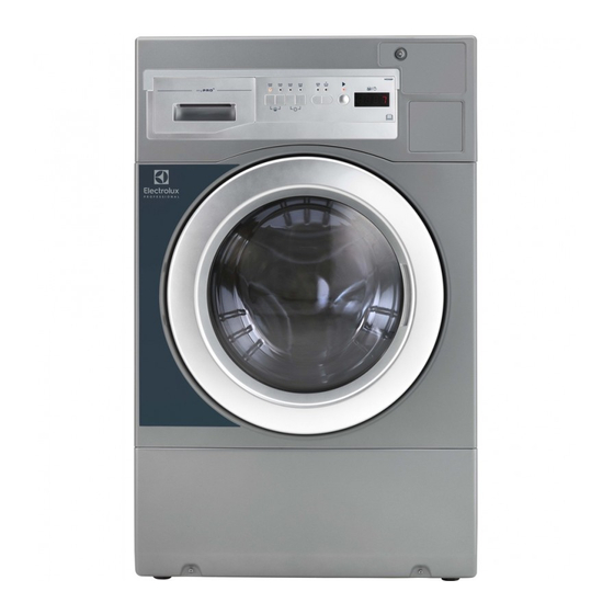
- Page 1 Installation manual Washer Extractor WE1100P 0020508979/EN Original instructions 2022.01.04...
-
Page 3: Table Of Contents
Contents Contents 1 Attention .............................5 2 Installation Manual ..........................5 3 Safety Precautions ..........................5 General safety information......................6 Commercial use only........................6 Ergonomics certification ......................6 Symbols............................7 4 Warranty terms and exclusions......................8 5 Technical Data ............................9 Drawing ............................9 Technical data .........................10 Connections ..........................10 6 Installation ............................11 Install the bottom cover plate .................... -
Page 5: Attention
Installation manual 1 Attention Four transportation bolts are installed in the rear of the machine, to protect the suspension and tub assembly from damage during shipment. Remove all four bolts and plastic tubes through which the bolts pass before operating the machine!! See instructions later in this manual. -
Page 6: General Safety Information
Installation manual – This appliance can be used by children aged from 8 years and above and persons with reduced physical, sensory or mental capabilities or lack of experience and knowl- edge if they have been given supervision or instruction concerning use of the appliance in a safe way and understand the hazards involved. -
Page 7: Symbols
Installation manual 3.4 Symbols Caution Caution, high voltage Read the instructions before using the machine... -
Page 8: Warranty Terms And Exclusions
Warranty will be applicable where the customer has used only genuine spare parts and has performed maintenance in accordance with Electrolux Professional user and maintenance documentation made available in paper or elec- tronic format. Electrolux Professional strongly recommends using Electrolux Professional approved cleaning, rinse and descaling agents to obtain optimal results and maintain product efficiency over time. -
Page 9: Technical Data
Installation manual 5 Technical Data 5.1 Drawing fig.W01595 Power line Air vent for safety Cold water Drain Coin meter Control panel Detergent container Door 1098 inch 43 1/4 12 3/16 30 1/8... -
Page 10: Technical Data
Installation manual 5.2 Technical data Weight, net Drum volume litres Drum diameter inch 21 7/8 Drum speed during wash Drum speed during extraction 1050 G-factor, max. Heating: Electricity Sound power/pressure level at extraction* dB(A) Sound power/pressure level at wash* dB(A) * Sound power levels measured according to ISO 60704. -
Page 11: Installation
Installation manual 6 Installation For safety, two people should install this product. Leave the machine on the transport pallet until it can be placed in the final, prepared position. First remove all the packing materials. Upon opening of the package, water drops may be seen in the plastic bag and the drum. -
Page 12: Removing Transportation Bolts
Installation manual 6.3 Removing Transportation Bolts 1. Unscrew the 4 bolts with a wrench. Remove the lower 2 bolts first, then the upper two. One of bolts retains the power cord of the washer to prevent operating without removing bolts. 2. -
Page 13: Recycling Instruction For Packaging
Installation manual 6.4 Recycling instruction for packaging fig.X02414 Fig. Description Code Type Carton box BC Corrugated Paper Packaging box sticker Synthetic paper Paper Bar code sticker Synthetic paper Paper Wrapping film LDPE Plastics Front corner protection Back corner protection Top protection Packing bottom Pallet Plywood... -
Page 14: Activating The Prewash Program
Installation manual 6.5 Activating the prewash program The prewash program is disabled by default. You need to enable it in service mode. The opening steps are as follows: 1. Press the service switch inside the money box once, all the lights are flashing. 2. -
Page 15: Install The Coin Meter (Coin Operated Models)
Installation manual 6.7 Install the Coin Meter (coin operated models) 1. Unlock the coin meter lock plate with the provided key. 2. Partially open the lock plate and slide to the left to remove it from the console. 3. Install the coin meter faceplate into the lock plate and then assemble the coin. 4. -
Page 16: Setting
Installation manual 6.9 Setting • Please install the machine close to a floor drain or open drain. • The machine should be well positioned and make sure that there is plenty of room for the users and personnel when maintenance needed. The figure shows minimum distance to a wall and/or other machines. •... -
Page 17: Water Connections
Installation manual 7 Water Connections Plumbing: This machine is approved for all UK applications as suitable for category 5. The product is listed in the WRAS regulations advisory scheme directory and is suitable for direct connection to mains drinking water. No special plumbing arrangements e.g. -
Page 18: Drain Connection
Installation manual 8 Drain Connection Connect the machine's drain hose to the back of the washer, using the spring clamp provided in the accessories package. Avoid sharp bends in the hose which may prevent proper draining. You can connect the drain hose to a sewer stand pipe. If you do this, make sure that the outlet hose will not come out of the stand pipe. -
Page 19: Connection Of External Liquid Supply Signals
Installation manual 9 Connection of External Liquid Supply Signals The machine can provide two "trigger signals" for external liquid supply injector pumps. The signals are 220-240V AC, 5A max, and must, therefore, be routed and connected in accordance with applicable codes. CN5 on the power module at the right-rear corner of the machine, and to your pumps. -
Page 20: Electrical Connections
Installation manual 10 Electrical Connections This appliance must be grounded. In the event of an electrical short circuit, grounding reduces the risk of electric shock by providing an escape wire for the electric current. This appliance is equipped with a cord having a grounding wire with a grounded plug. -
Page 21: Function Checks
Installation manual 11 Function Checks Perform the following checks once the machine is installed: • Open the water supply valves. • Press the START button or, if needed, insert coins and press START. Check: • That the drum rotates normally and that there are no unusual noises. •... -
Page 22: Preventive Maintenance
Installation manual 12 Preventive Maintenance To keep your machine in proper working order, follow the preventive maintenance recommendations provided below. The maintenance interval should be adjusted according to machine usage. Leave the loading door open when the machine is not in use. 12.1 Daily Check the door and door lock: •... -
Page 23: Disposal Information
Installation manual 13 Disposal information 13.1 Disposal of appliance at end of life Before disposing of the machine, make sure to carefully check its physical condition, and in particular any parts of the structure that can give or break during scrapping. The machine’s parts must be disposed of in a differentiated way, according to their different characteristics (e.g. - Page 24 Electrolux Professional AB 341 80 Ljungby, Sweden www.electroluxprofessional.com...
Need help?
Do you have a question about the WE1100P and is the answer not in the manual?
Questions and answers
I have not activated the pre wash programme before using my machine for the first time - what are the instructions to set this