Table of Contents
Advertisement
Quick Links
Advertisement
Table of Contents

Related Manuals for RTscan RT211


Summary of Contents for RTscan RT211
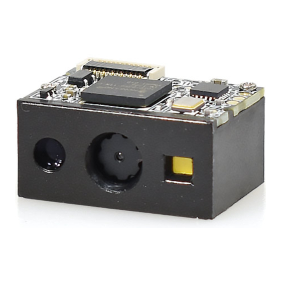
- Page 1 RT211 OEM Scan Engine Integration Guide...
-
Page 2: Table Of Contents
Table of Contents Chapter 1 Introduction Overview.......................................... 1 Illumination........................................1 Aimer..........................................1 Chapter 2 Installation......................................2 General Requirements....................................2 ESD..........................................2 Dust and Dirt......................................2 Thermal Considerations.................................... 2 Installation Orientation..................................... 3 Optics..........................................3 Window Placement....................................3 Window Material and Color..................................4 Scratch Resistance and Coating................................4 Window Size.......................................4 Ambient Light......................................6 Eye Safety........................................ - Page 3 Host Interface Connector....................................11 Dimensions of the Host Interface Connector (unit: mm)........................12 FFC Cable (unit: mm)....................................13 Communication Interfaces................................... 14 Control Interfaces......................................15 Reset......................................... 15 Trigger........................................15 Beeper........................................16 Good Read LED......................................17 Chapter 5 Development Tools..................................18 EVK..........................................18...
-
Page 4: Chapter 1 Introduction
Aimer The RT211 has a view finder that produces a red aiming pattern to help the user to easily position the target barcode within the engine’s field of view to increase scan efficiency. The aiming pattern can be turned On or... -
Page 5: Chapter 2 Installation
Chapter 1 Introduction General Requirements ESD protection has been taken into account when designing the RT211 and the engine is shipped in ESD safe packaging. Always exercise care when handling the engine outside its package. Be sure grounding wrist straps and properly grounded work areas are used. -
Page 6: Installation Orientation
Installation Orientation There are two threaded mounting holes in the bottom of the RT211 for fastening the engine to a mounting surface with machine screws. The following figure illustrates a front view of the RT211 after correct installation. Optics Window Placement The window should be positioned properly to let the illumination and aiming beams pass through as much as possible and no reflections back into the engine (reflections can degrade the reading performance). -
Page 7: Window Material And Color
Window Material and Color CIS’s responsiveness (mainly to wavelengths of red light)should be taken into consideration when choosing window material and color, in order to achieve the possible highest spectral transmission, lowest haze level and homogeneous refractive index. It is suggested to use PMMA or optical glass with spectral transmittance over 90% and haze less than 1%. - Page 8 Vertical:...
-
Page 9: Ambient Light
Eye Safety The RT211 uses LEDs to create the aiming and illumination beams. The LEDs are bright, but testing has been done to demonstrate that the engine is safe for its intended application under normal usage conditions. However, the user should avoid looking into the beam. -
Page 10: Mounting
Mounting The illustrations below show the mechanical mounting dimensions for the RT211. The structural design should leave some space between components. Front View (unit: mm) Side View (unit: mm) -
Page 11: Top View (Unit: Mm)
Top View (unit: mm) -
Page 12: Chapter 3 Electrical Specifications
Chapter 3 Electrical Specifications Power Supply Do not power up the RT211 until it is properly connected. Be sure the power is cut off before connecting a flexible cable to or disconnecting a flexible cable from the host interface connector. Hot-plugging could damage the engine. -
Page 13: Power Sequencing
Chapter 3 Electrical Specifications Power sequencing Please note: 1. In the above picture, A is the Boot’s startup completion time, B is the kernel’s startup completion time, C is the decode chip’s initialization completion time, and the total boot’s completion time is about 400ms. 2. -
Page 14: Chapter 4 Interfaces
Chapter 4 Interfaces Host Interface Connector The following table lists the pin functions of the 12-pin host interface connector on the RT211. PIN# Signal Function Not connected. 3.3V power supply. Power-supply ground. TTL level 232 receive data. TTL level 232 transmit data. -
Page 15: Dimensions Of The Host Interface Connector (Unit: Mm)
Chapter 4 Interfaces Dimensions of the Host Interface Connector (unit: mm) The RT211 uses a 12-pin FPC ZIF socket (bottom contact, model: 10051922-1210ELF) manufactured by FCI. The socket can be connected to a host device with an FFC cable. -
Page 16: Ffc Cable (Unit: Mm)
FFC Cable (unit: mm) A 12-pin FFC cable can be used to connect the RT211 to a host device. The cable design must be consistent with the specifications shown below. Use reinforcement material for the connectors on the cable and reduce... -
Page 17: Communication Interfaces
TTL-232: This interface is applicable to most system architectures. For those requiring RS-232, a TTL-232 to RS-232 conversion circuit is needed. The RT211’s TTL-232 interface supports baud rates from 1200bps to 115200bps; it does not support hardware or software flow control. Its default settings are 9600bps, 8 data bits, no parity check and1 stop bit. -
Page 18: Control Interfaces
(PIN 12) on the host interface connector low for over 10ms causes the RT211 to start a scan and decode session. If barcode is decoded, the RT211 waits for the voltage at the nTrig pin to turn high (or the trigger to be released) after sending the data to the Host. If the trigger is released during a scan attempt, the RT211 immediately stops decoding. -
Page 19: Beeper
Beeper The RT211 provides a pin (Buzz, PIN 9) on the host interface connector that provides a PWM output to an external driver circuit for generating audible feedback to the user to indicate statuses like power up or good read. The PWM output is not strong enough to drive a beeper, thus a beeper driver circuit is needed. -
Page 20: Good Read Led
Good Read LED The RT211 provides a pin (LED, PIN 10) on the host interface connector that can be used by an external driver circuit to drive an LED to indicate a Good Read status. When a good read occurs, the LED pin produces a high level output for about 300ms and then the signal is back to a low level. -
Page 21: Chapter 5 Development Tools
LED & LED driver circuit, trigger & reset buttons, TTL-232 to RS-232 converter & TTL-232 to USB converter, RS-232 & USB interfaces, etc. The RT211 can be connected to the EVK via a 12-pin FFC cable type 1 (contacts on the same side). Either USB connection or RS-232 connection can be used when connecting the EVK to a host device.
Need help?
Do you have a question about the RT211 and is the answer not in the manual?
Questions and answers