Table of Contents
Advertisement
Quick Links
Advertisement
Table of Contents

Related Manuals for RTscan RT211


Summary of Contents for RTscan RT211
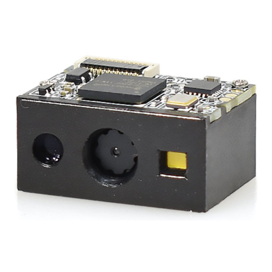
- Page 1 RT211 OEM Barcode Engine User Guide...
-
Page 2: Table Of Contents
Table of Contents Introduction.................................. 1 Chapter 1 Getting Started..............................1 About This Guide................................1 Barcode Programming..............................2 Configuring the RT211..............................3 Barcode Programming............................3 Command Programming............................3 Read Register................................4 Write Register.................................8 Save Register Data in EEPROM...........................12 Relationship between Programming Command and Serial Command............14 Programming Barcode Data............................ - Page 3 Manual Mode................................32 Chapter 3 Scan Mode..............................32 Continuous Mode..............................32 Decode Session Timeout............................. 33 Timeout between Decodes..........................33 Sense Mode................................34 Decode Session Timeout............................. 34 Timeout between Decodes..........................35 Image Stabilization Timeout..........................35 Sensitivity................................36 Command Trigger Mode............................. 37 Decode Session Timeout............................. 37 Illumination................................38 Chapter 4 Illumination &...
- Page 4 AIM 128................................50 Restore Factory Defaults............................. 50 Enable/Disable AIM 128............................. 50 EAN-8..................................51 Restore Factory Defaults............................. 51 Enable/Disable EAN-8............................51 Transmit Check Digit............................51 Add-On Code................................ 52 Add-On Code Required............................53 EAN-8 Extension..............................53 EAN-13..................................54 Restore Factory Defaults............................. 54 Enable/Disable EAN-13............................54 Transmit Check Digit............................
- Page 5 Transmit Appended “0”............................67 ITF-6..................................68 ITF-14................................... 69 Matrix 2 of 5................................. 70 Restore Factory Defaults............................. 70 Enable/Disable Matrix 2 of 5..........................70 Check Digit Verification............................71 Industrial 25.................................72 Restore Factory Defaults............................. 72 Enable/Disable Industrial 25..........................72 Check Digit Verification............................73 Standard 25................................74 Restore Factory Defaults............................. 74 Enable/Disable Standard 25..........................74 Check Digit Verification............................75 Code 39.................................
- Page 6 Enable/Disable RSS-14............................89 Transmit Application Identifier “01”......................... 89 RSS-Limited................................90 Restore Factory Defaults............................. 90 Enable/Disable RSS-Limited..........................90 Transmit Application Identifier “01”......................... 90 RSS-Expand................................91 Restore Factory Defaults............................. 91 Enable/Disable RSS-Expand..........................91 2D Symbologies..............................92 PDF417................................. 92 Restore Factory Defaults............................. 92 Enable/Disable PDF417............................92 Data Matrix................................93 Restore Factory Defaults.............................
-
Page 7: Chapter 1 Getting Started
This guide provides programming instructions for the RT211. Users can configure the RT211 by scanning the programming barcodes included in this manual. The RT211 has been properly configured for most applications and can be put into use without further configuration. Users may check Appendix A: Factory Defaults Table for reference. Throughout the manual,... -
Page 8: Barcode Programming
Powered by area-imaging technology, the RT211 features fast scanning and accurate decoding. Barcodes rotated at any angle can still be read with ease. When scanning a barcode, simply center the aiming beam or pattern projected by the RT211 over the barcode. -
Page 9: Configuring The Rt211
Configuring the RT211 There are two ways to configure the scanner: barcode programming and command programming. Barcode Programming The scanner can be configured by scanning programming barcodes. All user programmable features/options are described along with their programming barcodes/commands in the following sections. -
Page 10: Read Register
Read Register The read command is used to read the contents of 1 to 256 contiguous registers in the scanner. Prefix1 : 0x7E 0x00 Syntax: {Prefix1} {Types} {Lens} {Address} {Datas} {FCS} Types : 0x07 Lens : 0x01 Address: 0x0000~0x00FF, starting register address. Datas : 0x00~0xFF, number of registers to be read. - Page 11 unsigned int crc_cal_by_bit (unsigned char* ptr, unsigned int len) unsigned int crc = 0; while(len-- != 0) for(unsigned char i = 0x80; i != 0; i /= 2) crc *= 2; if((crc&0x10000) !=0) //After previvous CRC multiplied by 2, if the first bit is 1, then divide by 0x11021 crc ^= 0x11021;...
- Page 12 Reply: {Prefix2} {Types} {Lens} {Datas} {FCS} 1) Success message: Prefix2 : 0x02 0x00 Types : 0x00 (success) Lens : The number of data returned. If Lens=0x00, that means values of 256 contiguous registers are returned. Datas : 0x00~0xFF, data that are returned. : CRC-CCITT checksum.
- Page 13 Example: Read the content of register 0x000A 1) Read operation succeeds: 0x3E returned Enter: 0x7E 0x00 0x07 0x01 0x00 0x0A 0x01 0xEE 0x8A Response: 0x02 0x00 0x00 0x01 0x3E 0xE4 0xAC 2) FCS check fails: Enter: 0x7E 0x00 0x07 0x01 0x00 0x0A 0x01 0x11 0x22...
-
Page 14: Write Register
Write Register The write command is used to write contiguous registers (1 to 256 registers) in the scanner. Syntax: {Prefix1} {Types} {Lens} {Address} {Datas} {FCS} Prefix1 : 0x7E 0x00 (2 bytes) Types : 0x08 (1 byte) Lens : 0x00~0xFF (1 byte), byte count, also number of registers written. When Lens=0x00, 256 contiguous registers are to be written. - Page 15 unsigned int crc_cal_by_bit(unsigned char* ptr, unsigned int len) unsigned int crc = 0; while(len-- != 0) for(unsigned char i = 0x80; i != 0; i /= 2) crc *= 2; if((crc&0x10000) !=0) // After previvous CRC multiplied by 2, if the first bit is 1, then divide by 0x11021 crc ^= 0x11021;...
- Page 16 Response: {Prefix2} {Types} {Lens} {Datas} {FCS} 1) Success message: Prefix2 : 0x02 0x00 Types : 0x00 (success) Lens : 0x01 Datas : 0x00 : CRC-CCITT checksum (0x33 0x31) 2) FCS check failure message: Prefix2 : 0x02 0x00 Types : 0x01 (FCS check failure) Lens : 0x01 Datas : 0x00...
- Page 17 Example: Write 0x3E into register 0x000A 1) Write operation succeeds: Enter: 0x7E 0x00 0x08 0x01 0x00 0x0A 0x3E 0x4C 0xCF Response: 0x02 0x00 0x00 0x01 0x00 0x33 0x31 2) FCS check fails: Enter: 0x7E 0x00 0x08 0x01 0x00 0x0A 0x3E 0x11 0x22 Response: 0x02 0x00 0x01 0x01 0x00 0x04 0x01...
-
Page 18: Save Register Data In Eeprom
Save Register Data in EEPROM The save command is used to save register data into an external EEPROM. Syntax: {Prefix1} {Types} {Lens} {Address} {Datas} {FCS} Prefix1 : 0x7E 0x00 Types : 0x09 Lens : 0x01 Address: 0x0000 Datas : 0x00 : CRC-CCITT checksum (0xDE 0xC8) Response: {Prefix2} {Types} {Lens} {Datas} {FCS} 1) Success message:... - Page 19 3) Invalid command message: Prefix2 : 0x02 0x00 Types : 0x03 (invalid command) Lens : 0x01 Datas : 0x00 : CRC-CCITT checksum (0x6A 0x61)
-
Page 20: Relationship Between Programming Command And Serial Command
Relationship between Programming Command and Serial Command 1. Program general parameter with serial command A programming command (i.e. the characters under programming barcode) contains 7 characters. The function of each character is described in the table below. 1st Char 2nd Char ~3rd Char 4th Char~5th Char 6th Char~7th Char Remark... - Page 21 Enter: 0x7E 0x00 0x07 0x01 0x00 0x00 0x01 0x01 0x41 Response: 0x02 0x00 0x00 0x01 0xD4 0xB8 0xC8 Step 2: Calculate the value written to the register. Datas = (0xD4 & (! 0x03) ) + 0x02 = 0xD5 Step 3: Write the value into the register. Enter: 0x7E 0x00 0x08 0x01 0x00 0x00...
-
Page 22: Programming Barcode Data
Programming Barcode Data Programming barcode data (e.g. WFFD980) can be transmitted to the Host. To enable this feature, scan the barcode below. After the feature is enabled, programming barcodes will be handled as non-programming barcodes and they cannot be used to configure the scan scanner. The barcode data will be sent to the Host when a programming barcode is scanned and decoded. -
Page 23: Chapter 2 Communication Interfaces
Chapter 2 Communication Interfaces The RT211 provides an RS-232 interface and a USB interface to communicate with the host device. The host device can receive scanned data and send commands to control the scanner or to access/alter the configuration information of the scanner via the RS-232 or USB interface. -
Page 24: Baud Rate
Baud Rate Baud rate is the number of bits of data transmitted per second. Set the baud rate to match the Host requirements. ** 9600 1200 19200 2400 38400 4800 57600 14400 115200... -
Page 25: Usb Interface
USB Interface When the RT211 is connected to a host device through its USB interface, USB COM Port Emulation is enabled by default. User can switch between USB DATAPIPE, USB HID-KBW, USB COM Port Emulation and HID-POS, upon actual need. -
Page 26: Emulate Alt+Keypad
Emulate ALT+Keypad When Emulate ALT+Keypad is enabled, any ASCII character (0x00 - 0xFF) is sent over the numeric keypad no matter which keyboard type is selected. Since sending a character involves multiple keystroke emulations, this method appears less efficient. Hold the key “ALT” Enter the number corresponding to the ASCII character on the keypad. -
Page 27: Ascii Function Key Mapping Table
ASCII Function Key Mapping Table ASCII Value ASCII Value Function Key Function Key (HEX) (HEX)... -
Page 28: Usb Country Keyboard Types
USB Country Keyboard Types Keyboard layouts vary from country to country. All supported keyboard types are listed below. The default setting is US keyboard. ** U.S. Belgium Brazil Canada Czech Denmark Finland France... - Page 29 Germany, Austria Greece Hungary Israel Italy Latin America, South America Netherland Norway Poland Portugal...
- Page 30 Romania Russia Slovakia Spain Sweden Switzerland Turkey 1 Turkey 2 27 - UK 28 - Japan...
-
Page 31: Beep On Unknown Character
Beep on Unknown Character Due to the differences in keyboard layouts, some characters contained in barcode data may be unavailable on the selected keyboard. As a result, the scanner fails to transmit the unknown characters. Scan the appropriate barcode below to enable or disable the emission of beep when an unknown character is detected. -
Page 32: Caps Lock
Caps Lock The Caps Lock ON option can invert upper and lower case characters contained in barcode data. This inversion occurs regardless of the state of Caps Lock key on the Host’s keyboard. ** Caps Lock OFF Caps Lock ON Note: Emulate ALT+Keypad ON/ Convert All to Upper Case/ Convert All to Lower Case prevails over Caps Lock ON. -
Page 33: Convert Case
Convert Case Scan the appropriate barcode below to convert all bar code data to your desired case. ** No Case Conversion Convert All to Lower Case Convert All to Upper Case Example: When the Convert All to Lower Case feature is enabled, barcode data “AbC” is transmitted as “abc”. -
Page 34: Emulate Numeric Keypad
Emulate Numeric Keypad When this feature is disabled, sending barcode data is emulated as keystroke(s) on main keyboard. To enable this feature, scan the Emulate Numeric Keypad barcode. Sending a number (0-9) is emulated as keystroke on numeric keypad, whereas sending other character like “+”, “_”, “*” , “/” and “.” is still emulated as keystroke on main keyboard. -
Page 35: Usb Com Port Emulation
USB COM Port Emulation If you connect the scanner to the Host via a USB connection, the USB COM Port Emulation feature allows the Host to receive data in the way as a serial port does. However, you need to set communication parameters on the scanner to match the Host requirements. -
Page 36: Hid-Pos
HID-POS The HID-POS interface is recommended for new application programs. It can send up to 56 characters in a single USB report and appears more efficient than USB HID-KBW. Features: HID based, no custom driver required. Way more efficient in communication than USB HID-KBW and traditional RS-232 interface. ... -
Page 37: Acquire Scanned Data
Acquire Scanned Data After a barcode is decoded, the scanner sends an input report as below: Byte Report ID = 0x02 Barcode Length Decoded Data (1-56) 2-57 Reserved (1-4) 58-61 0x00 Decoded Data Continued VID/PID USB uses VID (Vendor ID) and PID (Product ID) to identify and locate a device. The VID is assigned by USB Implementers Forum. -
Page 38: Chapter 3 Scan Mode
Chapter 3 Scan Mode Manual Mode Manual Mode (default): A trigger pull activates a decode session. The decode session continues until the barcode is decoded or the trigger is released. ** Manual Mode Continuous Mode Continuous Mode: The scanner automatically activates a decode session. The decode session continues until the barcode is decoded or the decode session timeout expires. -
Page 39: Decode Session Timeout
Decode Session Timeout This parameter sets the maximum time decode session continues during a scan attempt. It is programmable in 0.1s increments from 0.1s to 25.5s. The default timeout is 5.0s. If the parameter is set to 0, the timeout is infinite. -
Page 40: Sense Mode
Sense Mode Sense Mode: The scanner waits for the image stabilization timeout to expire before activating a decode session every time it detects a change in ambient illumination. Decode session continues until the barcode is decoded or the decode session timeout expires. After a decode session ends, the scanner waits for the timeout between decodes to expire before beginning to monitor ambient illumination. -
Page 41: Timeout Between Decodes
Timeout between Decodes After a decode session ends, the scanner waits for the timeout between decodes to expire before beginning to monitor ambient illumination. This parameter is programmable in 0.1s increments from 0.1s to 25.5s. The default timeout is 1.0s. To learn how to program this parameter, see Appendix E: Parameter Programming Examples. -
Page 42: Sensitivity
Sensitivity Sensitivity specifies the degree of acuteness of the scanner’s response to changes in ambient illumination. The higher the sensitivity, the lower requirement in illumination change to trigger the scanner. You can select an appropriate degree of sensitivity that fits the ambient environment. High Sensitivity ** Medium Sensitivity Low Sensitivity... -
Page 43: Command Trigger Mode
Command Trigger Mode Command Trigger Mode: A decode session is activated by a host command (i.e. set the bit0 of register 0x0002 to “1”). The decode session continues until the barcode is decoded or the decode session timeout expires. Command Trigger Mode Decode Session Timeout This parameter sets the maximum time decode session continues during a scan attempt. -
Page 44: Chapter 4 Illumination & Aiming
Chapter 4 Illumination & Aiming Illumination A couple of illumination options are provided to improve the lighting conditions during every image capture: Normal (default): Illumination LED is turned on during image capture. OFF: Illumination LED is OFF all the time. ** Normal... -
Page 45: Aiming
Aiming When scanning/capturing image, the scanner projects an aiming beam which allows positioning the target barcode within its field of view and thus makes decoding easier. Normal (default): The scanner projects an aiming beam only during barcode scanning/capture. Always ON: Aiming beam is constantly ON after the scanner is powered on. OFF: Aiming beam is OFF all the time. -
Page 46: Chapter 5 Notification
Chapter 5 Notification Mute Mode Scanning the Enable Mute Mode can turn off all notification beeps. Scanning the Disable Mute mode to disable the Mute mode. Enable Mute Mode **Disable Mute Mode Good Read Beep Scanning the Good Read Beep off to turn off the beeper when the barcode is good read. Scanning the Good Read Beep On to turn on the beeper when the barcode is good read. -
Page 47: Good Read Beep Frequency
Good Read Beep Frequency ** Medium High Good Read Beep Duration 40ms ** 80ms 120ms... -
Page 48: Good Read Led
Good Read LED Good Read LED On Good Read LED Off Decode Result Notification If enabled, when a bad read occurs, “F” will be transmitted; when a good read occurs, “S” will be appended to the barcode data as the most left character. Note: This feature is NOT available in USB DATAPIPE mode. -
Page 49: Chapter 6 Prefix & Suffix
Chapter 6 Prefix & Suffix In many applications, barcode data needs to be edited and distinguished from one another. Usually AIM ID and Code ID can be used as identifiers, but in some special cases terminating character suffix like Carriage Return or Line Feed can also be the alternative. The scanner can be configured to transmit barcode data in the following format: [“F”/ “S”] + [Code ID] + [AIM ID] + [DATA] + [terminating character] Note: [DATA] must be transmitted while user can decide whether to transmit any of the rest parts. -
Page 50: Code Id Prefix
CODE ID Prefix Code ID can also be used to identify barcode type. For more information, refer to Appendix C: Code ID Table. Enable CODE ID Prefix ** Disable CODE ID Prefix You can choose to transmit original CODE ID or visible CODE ID by scanning the appropriate barcode below ( refer to Appendix C: Code ID Table ). -
Page 51: Terminating Character Suffix
Terminating Character Suffix A terminating character such as carriage return (CR) or carriage return/line feed pair (CRLF) or horizontal tab (TAB) can be used to mark the end of data. Disable Terminating Character Suffix Append CR ** Append CRLF Append TAB... -
Page 52: Chapter 7 Symbologies
Chapter 7 Symbologies Global Settings Enable/Disable All Symbologies If all symbologies are disabled, the scanner can only identify programming barcodes. Enable All Symbologies Disable All Symbologies Enable/Disable 1D Symbologies Scanning the following barcodes to enable or disable reading all 1D symbologies barcodes. Enable 1D Symbologies Disable 1D Symbologies Enable/Disable 2D Symbologies... -
Page 53: Video Reverse
Video Reverse The Video Reverse feature only applies to 2D barcodes. Regular barcode: Dark image on a bright background. Inverse barcode: Bright image on a dark background. The examples of regular barcode and inverse barcode are shown below. Regular Barcode Inverse Barcode Video Reverse is used to allow the scanner to read barcodes that are inverted. -
Page 54: 1D Symbologies
1D Symbologies Code 128 Restore Factory Defaults Restore the Factory Defaults of Code 128 Enable/Disable Code 128 ** Enable Code 128 Disable Code 128... -
Page 55: Ucc/Ean-128 (Gs1-128)
UCC/EAN-128 (GS1-128) Restore Factory Defaults Restore the Factory Defaults of UCC/EAN-128 Enable/Disable UCC/EAN-128 ** Enable UCC/EAN-128 Disable UCC/EAN-128... -
Page 56: Aim 128
AIM 128 Restore Factory Defaults Restore the Factory Defaults of AIM 128 Enable/Disable AIM 128 ** Enable AIM 128 Disable AIM 128... -
Page 57: Ean-8
EAN-8 Restore Factory Defaults Restore the Factory Defaults of EAN-8 Enable/Disable EAN-8 ** Enable EAN-8 Disable EAN-8 Transmit Check Digit EAN-8 is 8 digits in length with the last one as its check digit used to verify the integrity of the data. ** Transmit EAN-8 Check Digit Do Not Transmit EAN-8 Check Digit... -
Page 58: Add-On Code
Add-On Code An EAN-8 barcode can be augmented with a two-digit or five-digit add-on code to form a new one. In the examples below, the part surrounded by blue dotted line is an EAN-8 barcode while the part circled by red dotted line is add-on code. -
Page 59: Add-On Code Required
Add-On Code Required When EAN-8 Add-On Code Required is selected, the scanner will only read EAN-8 barcodes that contain add-on codes. EAN-8 Add-On Code Required ** EAN-8 Add-On Code Not Required EAN-8 Extension Disable EAN-8 Zero Extend: Transmit EAN-8 barcodes as is. Enable EAN-8 Zero Extend: Add five leading zeros to decoded EAN-8 barcodes to extend to13 digits. -
Page 60: Ean-13
EAN-13 Restore Factory Defaults Restore the Factory Defaults of EAN-13 Enable/Disable EAN-13 ** Enable EAN-13 Disable EAN-13 Transmit Check Digit EAN-13 is 13 digits in length with the last one as its check digit used to verify the integrity of the data. ** Transmit EAN-13 Check Digit Do Not Transmit EAN-13 Check Digit... -
Page 61: Add-On Code
Add-On Code An EAN-13 barcode can be augmented with a two-digit or five-digit add-on code to form a new one. In the examples below, the part surrounded by blue dotted line is an EAN-13 barcode while the part circled by red dotted line is add-on code. -
Page 62: Add-On Code Required
Add-On Code Required When EAN-13 Add-On Code Required is selected, the scanner will only read EAN-13 barcodes that contain add-on codes. EAN-13 Add-On Code Required ** EAN-13 Add-On Code Not Required... -
Page 63: Issn
ISSN Restore Factory Defaults Restore the Factory Defaults of ISSN Enable/Disable ISSN Enable ISSN ** Disable ISSN... -
Page 64: Isbn
ISBN Restore Factory Defaults Restore the Factory Defaults of ISBN Enable/Disable ISBN ** Enable ISBN Disable ISBN Set ISBN Format ** ISBN-13 ISBN-10... -
Page 65: Upc-E
UPC-E Restore Factory Defaults Restore the Factory Defaults of UPC-E Enable/Disable UPC-E ** Enable UPC-E Disable UPC-E Transmit Check Digit UPC-E is 8 digits in length with the last one as its check digit used to verify the integrity of the data. ** Transmit UPC-E Check Digit Do Not Transmit UPC-E Check Digit... -
Page 66: Add-On Code
Add-On Code A UPC-E barcode can be augmented with a two-digit or five-digit add-on code to form a new one. In the examples below, the part surrounded by blue dotted line is a UPC-E barcode while the part circled by red dotted line is add-on code. -
Page 67: Add-On Code Required
Add-On Code Required When UPC-E Add-On Code Required is selected, the scanner will only read UPC-E barcodes that contain add-on codes. UPC-E Add-On Code Required ** UPC-E Add-On Code Not Required Transmit System Character The first character of UPC-E barcode is the system character “0”. Transmit System Character “0”... -
Page 68: Upc-A
UPC-A Restore Factory Defaults Restore the Factory Defaults of UPC-A Enable/Disable UPC-A ** Enable UPC-A Disable UPC-A Transmit Check Digit UPC-A is 13 digits in length with the last one as its check digit used to verify the integrity of the data. ** Transmit UPC-A Check Digit Do Not Transmit UPC-A Check Digit... -
Page 69: Add-On Code
Add-On Code A UPC-A barcode can be augmented with a two-digit or five-digit add-on code to form a new one. In the examples below, the part surrounded by blue dotted line is a UPC-A barcode while the part circled by red dotted line is add-on code. -
Page 70: Add-On Code Required
Add-On Code Required When UPC-A Add-On Code Required is selected, the scanner will only read UPC-A barcodes that contain add-on codes. UPC-A Add-On Code Required ** UPC-A Add-On Code Not Required Transmit Preamble Character Preamble characters (Country Code and System Character) can be transmitted as part of a UPC-A barcode. Select one of the following options for transmitting UPC-A preamble to the host device: transmit system character only or transmit system character and country code (“0”... -
Page 71: Interleaved 2 Of 5
Interleaved 2 of 5 Restore Factory Defaults Restore the Factory Defaults of Interleaved 2 of 5 Enable/Disable Interleaved 2 of 5 ** Enable Interleaved 2 of 5 Disable Interleaved 2 of 5... -
Page 72: Check Digit Verification
Check Digit Verification A check digit is optional for Interleaved 2 o 5 and can be added as the last digit. It is a calculated value used to verify the integrity of the data. Disable: The scanner transmits Interleaved 2 of 5 barcodes as is. Do Not Transmit Check Digit After Verification: The scanner checks the integrity of all Interleaved 2 of 5 barcodes to verify that the data complies with the check digit algorithm. -
Page 73: Transmit Appended "0
Transmit Appended “0” If an Interleaved 2 of 5 barcode contains an odd number of characters, a leading zero must be appended to the barcode. Scan the appropriate barcode to choose whether to transmit the appended “0”. ** Transmit Appended “0” Do Not Transmit Appended “0”... -
Page 74: Itf-6
ITF-6 ITF-6 is a special kind of Interleaved 2 of 5 with a length of 6 characters and the last character as the check character. Restore the Factory Defaults of ITF-6 ** Disable ITF-6 Enable ITF-6 But Do Not Transmit Check Digit Enable ITF-6 and Transmit Check Digit Note: It is advisable not to enable ITF-6 and Interleaved 2 of 5 at the same time. -
Page 75: Itf-14
ITF-14 ITF-14 is a special kind of Interleaved 2 of 5 with a length of 14 characters and the last character as the check character. Restore the Factory Defaults of ITF-14 Disable ITF-14 Enable ITF-14 But Do Not Transmit Check Digit Enable ITF-14 and Transmit Check Digit Note: It is advisable not to enable ITF-14 and Interleaved 2 of 5 at the same time. -
Page 76: Matrix 2 Of 5
Matrix 2 of 5 Restore Factory Defaults Restore the Factory Defaults of Matrix 2 of 5 Enable/Disable Matrix 2 of 5 ** Enable Matrix 2 of 5 Disable Matrix 2 of 5... -
Page 77: Check Digit Verification
Check Digit Verification Disable Do Not Transmit Check Digit After Verification Transmit Check Digit After Verification... -
Page 78: Industrial 25
Industrial 25 Restore Factory Defaults Restore the Factory Defaults of Industrial 25 Enable/Disable Industrial 25 ** Enable Industrial 25 Disable Industrial 25... -
Page 79: Check Digit Verification
Check Digit Verification ** Disable Do Not Transmit Check Digit After Verification Transmit Check Digit After Verification... -
Page 80: Standard 25
Standard 25 Restore Factory Defaults Restore the Factory Defaults of Standard 25 Enable/Disable Standard 25 ** Enable Standard 25 Disable Standard 25... -
Page 81: Check Digit Verification
Check Digit Verification ** Disable Do Not Transmit Check Digit After Verification Transmit Check Digit After Verification... -
Page 82: Code 39
Code 39 Restore Factory Defaults Restore the Factory Defaults of Code 39 Enable/Disable Code 39 ** Enable Code 39 Disable Code 39 Transmit Start/Stop Character Code39 has each character before and after the barcode data as start character and stop character, it can be configured whether to output Transmit Start/Stop Character Do Not Transmit Start/Stop Character... -
Page 83: Check Digit Verification
Check Digit Verification Disable Do Not Transmit Check Digit After Verification Transmit Check Digit After Verification Enable/Disable Code 39 Full ASCII The scanner can be configured to identify all ASCII characters by scanning the appropriate barcode below. Enable Code 39 Full ASCII ** Disable Code 39 Full ASCII... -
Page 84: Codabar
Codabar Restore Factory Defaults Restore the Factory Defaults of Codabar Enable/Disable Codabar ** Enable Codabar Disable Codabar... -
Page 85: Check Digit Verification
Check Digit Verification Disable Do Not Transmit Check Digit After Verification Transmit Check Digit After Verification Transmit Start/Stop Character Codabar has each character before and after the barcode data as start character and stop character, the scanner can be configured whether to output it. - Page 86 Start/Stop Character Format Codabar's start and stop characters can be configured as one of the following formats. ** ABCD/ABCD as the Start/Stop Character ABCD/TN*E as the Start/Stop Character abcd/abcd as the Start/Stop Character abcd/tn*e as the Start/Stop Character...
-
Page 87: Code 93
Code 93 Restore Factory Defaults Restore the Factory Defaults of Code 93 Enable/Disable Code 93 ** Enable Code 93 Disable Code 93... -
Page 88: Check Digit Verification
Check Digit Verification Disable Do Not Transmit Check Digit After Verification Transmit Check Digit After Verification... -
Page 89: Code 11
Code 11 Restore Factory Defaults Restore the Factory Defaults of Code 11 Enable/Disable Code 11 ** Enable Code 11 Disable Code 11... -
Page 90: Check Digit Verification
Check Digit Verification Disable ** One Check Digit, MOD11 Two Check Digits, MOD11/MOD11 Two Check Digits, MOD11/MOD9 One Check Digit, MOD11 (Len <= 11) One Check Digit, MOD11 (Len <= 11) Two Check Digits, MOD11/MOD11 (Len > 11) Two Check Digits, MOD11/MOD9 (Len > 11) ** Transmit Check Digit Do Not Transmit Check Digit... -
Page 91: Plessey
Plessey Restore Factory Defaults Restore the Factory Defaults of Plessey Enable/Disable Plessey ** Enable Plessey Disable Plessey... -
Page 92: Check Digit Verification
Check Digit Verification Disable ** Do Not Transmit Check Digit After Verification Transmit Check Digit After Verification... -
Page 93: Msi-Plessey
MSI-Plessey Restore Factory Defaults Restore the Factory Defaults of MSI-Plessey Enable/Disable MSI-Plessey ** Enable MSI-Plessey Disable MSI-Plessey... -
Page 94: Check Digit Verification
Check Digit Verification Disable ** One Check Digit, MOD10 Two Check Digits, MOD10/MOD10 Two Check Digits, MOD10/MOD11 ** Transmit Check Digit Do Not Transmit Check Digit... -
Page 95: Rss-Limited
RSS-Limited Restore Factory Defaults Restore the Factory Defaults of RSS-14 Enable/Disable RSS-14 ** Enable RSS-14 Disable RSS-14 Transmit Application Identifier “01” ** Transmit Application Identifier “01” Do Not Transmit Application Identifier “01”... -
Page 96: Rss-Limited
RSS-Limited Restore Factory Defaults Restore the Factory Defaults of RSS-Limited Enable/Disable RSS-Limited ** Enable RSS-Limited Disable RSS-Limited Transmit Application Identifier “01” ** Transmit Application Identifier “01” Do Not Transmit Application Identifier “01”... -
Page 97: Rss-Expand
RSS-Expand Restore Factory Defaults Restore the Factory Defaults of RSS-Expand Enable/Disable RSS-Expand ** Enable RSS-Expand Disable RSS-Expand... -
Page 98: 2D Symbologies
2D Symbologies PDF417 Restore Factory Defaults Restore the Factory Defaults of PDF417 Enable/Disable PDF417 ** Enable PDF417 Disable PDF417... -
Page 99: Data Matrix
Data Matrix Restore Factory Defaults Restore the Factory Defaults of Data Matrix Enable/Disable Data Matrix ** Enable Data Matrix Disable Data Matrix Rectangular Barcodes ** Decode Rectangular Barcodes Do Not Decode Rectangular Barcodes... -
Page 100: Mirror Images
Mirror Images ** Decode Unmirrored DM Only Decode Mirrored DM Only Decode Both... -
Page 101: Qr Code
QR Code Restore Factory Defaults Restore the Factory Defaults of QR Code Enable/Disable QR Code ** Enable QR Code Disable QR Code Micro QR ** Enable Micro QR Disable Micro QR Mirrored Micro QR Decode Mirrored Micro QR ** Do Not Decode Mirrored Micro QR... -
Page 102: Chinese Sensible Code
Chinese Sensible Code Restore Factory Defaults Restore the Factory Defaults of Chinese Sensible Code Enable/Disable Chinese Sensible Code ** Enable Chinese Sensible Code Disable Chinese Sensible Code... -
Page 103: Appendix
Appendix Appendix A: Factory Defaults Table Parameter Factory Default Remark Barcode Programming Enabled Programming Barcode If Send Programming Barcode Data is Programming Barcode Data Do not send enabled, barcode programming will be disabled. Baud Rate 9600 Communication Interfaces Parity Check None TTL-232 Interface Number of Data Bits... - Page 104 Decode Session Timeout 3.0s 0.1-25.5s; increment:0.1s; 0:infinite. Parameter Factory Default Remark Continuous Mode Timeout between Decodes 1.0s 0-25.5s; increment:0.1s Decode Session Timeout 3.0s 0.1-25.5s; increment:0.1s; 0: infinite. Timeout between Decodes 1.0s 0-25.5s; increment:0.1s Sense Mode Image Stabilization Timeout 0.4s 0-25.5s; increment:0.1s Sensitivity Medium Command Trigger ModeDecode Session Timeout...
- Page 105 Parameter Factory Default Remark Video Reverse Disabled Applicable to all symbologies. Symbologies Code 128 Enabled Code 128 UCC/EAN-128 ( GS1-128 ) UCC/EAN-128 Enabled AIM 128 Enabled AIM 128 EAN-8 Enabled EAN-8 Check Digit Transmit 2-Digit Add-On Code Disabled 5-Digit Add-On Code Disabled Add-On Code Not required...
- Page 106 Parameter Factory Default Remark Enabled UPC-E UPC-E Transmit Check Digit Disabled 2-Digit Add-On Code Disabled 5-Digit Add-On Code Not required Add-On Code Disabled Extend to UPC-A Do not transmit System Character “0” Enabled UPC-A UPC-A Transmit Check Digit Disabled 2-Digit Add-On Code Disabled 5-Digit Add-On Code Not required...
- Page 107 Parameter Factory Default Remark Industrial 25 Enabled Industrial 25 Check Digit Verification Disabled Check Digit Do not transmit Standard 25 Enabled Standard 25 Check Digit Verification Disabled Check Digit Do not transmit Code 39 Enabled Code 39 Check Digit Verification Disabled Check Digit Do not transmit...
- Page 108 Parameter Factory Default Remark Plessey Enabled Plessey Check Digit Verification Enabled Check Digit Do not transmit MSI-Plessey Enabled MSI-Plessey check digit, Check Digit Verification MOD10 Check Digit Transmit RSS-14 Enabled RSS-14 AI (Application Identifier) Transmit RSS-Limited Enabled RSS-Limited AI (Application Identifier) Transmit RSS-Expand Enabled...
-
Page 109: Appendix B: Aim Id Table
Appendix B: AIM ID Table Code 128 Standard Code 128 Symbology AIM ID Remark UCC/EAN 128 FNC1 is the character right after the start character (GS1-128) AIM 128 FNC1 is the 2nd character after the start character Standard EAN-8 EAN-8 ]E4….]E1…... - Page 110 One check digit, MOD 43; transmit check digit Symbology AIM ID Remark One check digit, MOD 43; do not transmit check digit Full ASCII enabled; no check digit verification Full ASCII enabled; MOD43; transmit check digit Full ASCII enabled; MOD43; do not transmit check digit Standard Codabar Codabar Transmit check digit after verification...
- Page 111 QR1 (comply with AIM ISS 97-001 specifications) Symbology AIM ID Remark QR2 (2005 symbol), ECI protocol not supported QR2 (2005 symbol), ECI protocol supported QR2 (2005 symbol), ECI protocol not supported; FNC1 is the character right after the start character QR Code QR2 (2005 symbol), ECI protocol supported;...
-
Page 112: Appendix C: Code Id Table
Appendix C: Code ID Table Code 128 FNC3 A(0x41) Symbology Original Code ID Visible Code ID Code 128 B(0x42) UCC/EAN 128 C(0x43) EAN-8 D(0x44) EAN-13 E(0x45) UPC-E F(0x46) UPC-A G(0x47) Interleaved 2 of 5 H(0x48) ITF-14 I(0x49) ITF-6 J(0x4A) Code 39 M(0x4D) Codabar O(0x4F) -
Page 113: Appendix D: Ascii Table
Appendix D: ASCII Table (Null char.) Char (Start of Header) (Start of Text) (End of Text) (End of Transmission) (Enquiry) (Acknowledgment) (Bell) (Backspace) (Horizontal Tab) (Line Feed) (Vertical Tab) (Form Feed) (Carriage Return) (Shift Out) (Shift In) (Data Link Escape) (XON) (Device Control 1) (Device Control 2) (XOFF) (Device Control 3) - Page 114 (Request to Send) Char (Unit Separator) (Space) (Exclamation Mark) " (Double Quote) (Number Sign) (Dollar Sign) (Percent) & (Ampersand) (Single Quote) (Left / Opening Parenthesis) (Right / Closing Parenthesis) (Asterisk) (Plus) (Comma) (Minus / Dash) (Dot) (Forward Slash) (Colon) (Semi-colon) <...
- Page 115 > (Greater Than) Char (Question Mark) (AT Symbol) (Left / Opening Bracket) (Back Slash) (Right / Closing Bracket)
- Page 116 (Caret / Circumflex) Char (Underscore) (Grave Accent) (Left/ Opening Brace) (Vertical Bar) (Right/Closing Brace) (Tilde) (Delete)
-
Page 117: Appendix E: Parameter Programming Examples
Appendix E: Parameter Programming Examples The following examples show you how to program parameters by scanning programming barcodes. The “xxxxx” in text points the setup code of the this function. Program the Decode Session Timeout Scan the Decode Session Timeout barcode. Example: Set the decode session timeout to 5.0s, please follow: Scan the numeric barcodes “5”... -
Page 118: Appendix F: Digit Barcodes
Appendix F: Digit Barcodes 0 ~ 5... - Page 119 6 ~ 9...
- Page 120 A ~ F...
-
Page 121: Appendix G: Save/Cancel Barcodes
Appendix G: Save/Cancel Barcodes After reading numeric barcode(s), you need to scan the Save barcode to save the data. If you scan the wrong digit(s), you can either scan the Cancel the Last Digit barcode and then the correct digit, or scan the Cancel All Digits barcode and then the digits you want. -
Page 122: Appendix H: Frequently-Used Serial Commands
02 00 00 02 1A 00 SS SS 115200 Note: SS SS: CRC-CCITT checksum. 3A, BIT innovation building, Gaoxin South RTSCAN TECHNOLOGY LIMITED 9th Rd, Nanshan District, Shenzhen, China Tel: +86 - (0) 755-23762089 Fax: +86 - (0) 755-82037749 Email: info@rtscan.net...
Need help?
Do you have a question about the RT211 and is the answer not in the manual?
Questions and answers