
Related Manuals for RTscan RT207


Summary of Contents for RTscan RT207
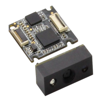
- Page 1 Integration Guide RT207 OEM 2D Barcode Scanner Engine Integration Guide Revision History Version Description Date V1.0.0 Initial release. August 14, 2015...
-
Page 2: Table Of Contents
Table of Contents Chapter 1 Introduction..............................1 Overview.................................... 1 Illumination..................................1 Aimer....................................1 Chapter 2 Installation.................................2 General Requirements..............................2 ESD....................................2 Dust and Dirt.................................2 Ambient Environment..............................2 Thermal Considerations.............................. 2 Installation Orientation..............................3 Optics....................................4 Window Placement..............................4 Window Material and Color............................4 Scratch Resistance and Coating...........................5 Window Size..................................5 Ambient Light................................ - Page 3 Operating Current..............................11 Chapter 4 Interfaces................................. 12 Host Interface Connector............................... 12 Dimensions of the Host Interface Connector (unit: mm)..................13 Flat Flexible Cable (unit: mm)...........................14 Communication Interfaces............................. 15 Control Interfaces................................16 Reset.................................... 16 Trigger..................................16 Beeper..................................17 Good Read LED................................18 Chapter 5 Development Tools............................19 EVK....................................
-
Page 4: Chapter 1 Introduction
Aimer The RT207 has a view finder that produces a solid circle-shaped aiming pattern to help the user to easily position the target bar code within the engine’s field of view to increase scan efficiency. The aiming pattern... -
Page 5: Chapter 2 Installation
Chapter 2 Installation General Requirements ESD protection has been taken into account when designing the RT207 and the engine is shipped in ESD safe packaging. Always exercise care when handling the engine outside its package. Be sure grounding wrist straps and properly grounded work areas are used. -
Page 6: Installation Orientation
Integration Guide Installation Orientation There are two threaded mounting holes in the bottom of the RT207 for fastening the engine to a mounthing surface with machine screws. The following figure illustrates a front view of the RT207 after correct installation. -
Page 7: Optics
Integration Guide Optics Window Placement The window should be positioned properly to let the illumination and aiming beams pass through as much as possible and no reflections back into the engine (reflections can degrade the reading performance). The window should be mounted close to the front of the engine (parallel). The maximum distance is measured from the front of the engine housing to the furthest surface of the window. -
Page 8: Scratch Resistance And Coating
Integration Guide Scratch Resistance and Coating Scratch on the window can greatly reduce the performance of the RT207. It is suggested to use abrasion resistant window material or coating. Window Size The window must not block the field of view and should be sized to accommodate the aiming and illumination envelopes shown below. - Page 9 Integration Guide Vertical:...
-
Page 10: Ambient Light
Eye Safety The RT207 has no lasers. It uses red LEDs to create illumination and aiming beams. The LEDs are bright, but testing has been done to demonstrate that the engine is safe for its intended application under normal usage... -
Page 11: Mounting
Integration Guide Mounting The illustrations below show the mechanical mounting dimensions for the RT207. The structural design should leave some space between components. Front View (unit: mm) Side View (unit: mm) -
Page 12: Top View (Unit: Mm)
Integration Guide Top View (unit: mm) Mounting Hole M1.6 2.0mm... -
Page 13: Chapter 3 Electrical Specifications
Chapter 3 Electrical Specifications Power Supply Do not power up the RT207 until it is properly connected. Be sure the power is cut off before connecting a flexible cable to or disconnecting a flexible cable from the host interface connector. Hot-plugging could damage the engine. -
Page 14: Dc Characteristics
Integration Guide DC Characteristics Operating Voltage Ta=25℃ Parameter Description Minimum Typical Maximum Unit Voltage Drain Drain High Level Input Voltage -0.5 Low Level Input Voltage High Level Output -0.3 Voltage Low Level Output Voltage Operating Current Ta=25℃,V =3.3V Operating Current Standby Current Sleep Current 210mA... -
Page 15: Chapter 4 Interfaces
Good Read LED section. Reset signal input: Driving this pin low for 100us-500us resets the Reset engine. Trigger signal input: Driving this pin low for at least 10ms causes the nTrig RT207 to start a scan and decode session. -
Page 16: Dimensions Of The Host Interface Connector (Unit: Mm)
Integration Guide Dimensions of the Host Interface Connector (unit: mm) The RT207 uses a 12-pin FPC ZIF socket (bottom contact, model: 10051922-1210EHLF) manufactured by FCI. The socket can be connected to a host device with a flat flexible cable. -
Page 17: Flat Flexible Cable (Unit: Mm)
Flat Flexible Cable (unit: mm) A 12-pin flat flexible cable can be used to connect the RT207 to a host device. The cable design must be consistent with the specifications shown below. Use reinforcement material for the connectors on the cable... -
Page 18: Communication Interfaces
Integration Guide Communication Interfaces The RT207 can communicate with the host device via its TTL-232 interface. This interface is applicable to most system architectures. For those requiring RS-232, a TTL-232 to RS-232 conversion circuit is needed. The RT207’s TTL-232 interface supports baud rates from 1200bps to 115200bps; it does not support hardware flow control. -
Page 19: Control Interfaces
(PIN 12) on the host interface connector low for over 10ms causes the RT207 to start a scan and decode session. If barcode is decoded, the RT207 waits for the voltage at the nTrig pin to turn high (or the trigger to be released) after sending the data to the Host. If the trigger is released during a scan attempt, the RT207 immediately stops decoding. -
Page 20: Beeper
Integration Guide Beeper The RT207 provides a pin (Buzz, PIN 9) on the host interface connector that provides a PWM output to an external driver circuit for generating audible feedback to the user to indicate statuses like power up or good read. -
Page 21: Good Read Led
Good Read LED The RT207 provides a pin (LED, PIN 10) on the host interface connector that can be used by an external driver circuit to drive an LED to indicate a Good Read status. When a good read occurs, the LED pin produces a high level output and then the signal is back to a low level. -
Page 22: Chapter 5 Development Tools
The EVK is provided to help users to test and evaluate the RT207, which contains beeper & beeper driver circuit, LED & LED driver circuit, trigger & reset buttons, TTL-232 to USB converter, RS-232 & USB interfaces, etc.
Need help?
Do you have a question about the RT207 and is the answer not in the manual?
Questions and answers