
Related Manuals for ABB MNS


Summary of Contents for ABB MNS
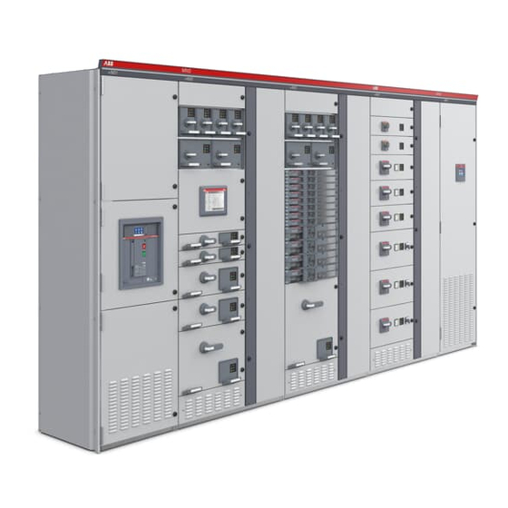
- Page 1 Rozdzielnica niskiego napięcia ® Dokumentacja Techniczno-Ruchowa Service Manual...
- Page 2 Page Konsekwencje w przypadku nieprzestrzegania zasad zapisa- Consequences in the event of non-compliance nych w DTR MNS ABB shall not assume any liability for any of the ABB nie ponosi odpowiedzialności za żadne z poniższych zda- following events: rzeń: Negligent handling of the low-voltage switchgear system and ...
- Page 3 Spis treści Str./ Content Page Dokumentacja Techniczno-Ruchowa Manual Service Montaż, uruchomienie, obsługa i konserwacja Erection, Commissioning, Operation and Maintenance Numer dokumentu / Publication No. 1TGC 902006 M0403 Wydanie / Edition 2013 MNS DTR / MNS Service...
-
Page 4: Table Of Contents
Fused load-break switch type XR and SR Moduły wysuwne rozmiaru 8E/4 i 8E/2 Withdrawable units size 8E/4 and 8E/2 Moduły wysuwne rozmiaru 4E do 48E Withdrawable units size 4E up to 48E Informacje dodatkowe Special information MNS DTR / MNS Service... - Page 5 Withdrawable technique Przebudowa przedziału aparatowego przezna- Conversion and change of czonego do montażu modułów wysuwnych withdrawable module compartments Ocena styków głównych MNS w trakcie prze- Examination of MNS contact systems within glądu the scope of plant revisions Smarowanie powierzchni stykowych Greasing of contact areas Smarowanie mechanizmu napędowego modu-...
-
Page 6: Opis Techniczny
Weryfikacja rozwiązania poprzez testy. Jeżeli rozwiązanie było przebadane zgodnie z normą IEC 60439-1, to rezultaty tego badania zapew- niają spełnienie wymogów norm IEC61439 -1 / -2, a weryfikacja tych rozwiązań nie jest powtarzana. Zależnie od wyposażenia elektrycznego. MNS DTR / MNS Service... - Page 7 Design verification by testing: When an assembly has previously been tested in accordance with IEC 60439-1 , and the results fulfil the requirements of IEC61439 -1 / -2, the verification of these requirements need not to be repeated Depending on the electrical equipment. MNS DTR / MNS Service...
-
Page 8: Konstrukcja Mechaniczna
ścianami działowymi. Celki mogą być przystosowane do are separated by separation walls if required. Cubicles can be obsługi z jednej lub z dwóch stron rozdzielnicy. arranged for front operation or front and rear operation. MNS DTR / MNS Service... -
Page 9: Moduły Wysuwne Rozmiaru 8E/4
Moduły wysuwne wielkości 24E i 16E Withdrawable module size Rys. 2 / Fig. 2 24E and 16E Wyposażenie montowane od przodu Osłona z kratką wentyla- (przykład) cyjną Front mounted equipment (example) Cover with ventilation louvers MNS DTR / MNS Service... -
Page 10: Busbar System
Przy sto- technique. If using the metal separation wall (MSW) only one sowaniu metalowej ściany wielofunkcyjnej (MSW) można zain- 4-pole distribution bar system can be installed. stalować tylko jeden 4-polowy system szyn zbiorczych. MNS DTR / MNS Service... - Page 11 Wspornik szynowy 3- lub 4-polowy Busbar support 3- or 4-pole Szyny zbiorcze Busbar Płytka dociskowa szyn Busbar holding plate Szyna N N busbar Rys. 3 / Fig. 3 System szyn 4-polowy Busbar system with outlined 4 pole MNS DTR / MNS Service...
- Page 12 N bus insulator Połączenie szyn PE/PEN (26) PE/PEN connection Szyna N N bar Szyna PE/PEN PE/PEN busbar Rys. 4 / Fig. 4 Szyny ochronne (PE) i szyny neutralne (N) Protective bars (PE) and neutral bars (N) MNS DTR / MNS Service...
- Page 13 Rys. 5 / Fig. 5 Szyny dystrybucyjne w wykonaniu otwartym (układ bez ściany wielofunkcyjnej) Open version of distribution bars (version without multi-function separator) MNS DTR / MNS Service...
- Page 14 Szyny rozdzielcze zamontowane w ścianie wielofunkcyjnej (MFS) z zestawami do przyłączeń kabli odpływowych i osłonami szyn 2E Cubicle distribution bar embedded in multi-function separator (MFS) with outgoing cable connection unit and 2E distribution bar covers MNS DTR / MNS Service...
- Page 15 Metalowa ściana wielo- funkcyjna Metal seperation wall Rys. 7 / Fig. 7 Szyny rozdzielcze zamocowane w metalowej ścianie wielofunkcyjnej (MSW) z osłonami szyn Distribution bars embedded in metal separation wall (MSW) with distribution bar covers MNS DTR / MNS Service...
- Page 16 MNS DTR / MNS Service...
-
Page 17: Modular Add-On Parts
Rys. 9 Fig. 9 Celka z wysuwnym wyłącznikiem powietrznym typu Emax (z niszą Withdrawable circuit breaker type Emax (with measuring recess) pomiarową), jako pole zasilające rozdzielnicy MCC in narrow cubicle as feeder for MCC MNS DTR / MNS Service... - Page 18 (left and right), bushing side walls for outgoing cables and kabli odpływowych oraz dolna ściana przedziału oddzielająca od compartment bottom plate, which separates the modules from siebie moduły (patrz Rys. 8). each other (see fig. 8). MNS DTR / MNS Service...
- Page 19 600 mm 600 mm. Moduły są przymocowane bezpośrednio do ramy montażowej MNS The modules are fastened directly to the MNS frame using tap- przy użyciu śrub samogwintujących umieszczonych w uchwytach ping screws secured with a screw cage.
- Page 20 400mm i 600mm and 600mm width Rys. 10.2 Rys. 10.2 Wewnętrzne przegrody oddzielające przedział aparatowy od prze- Optional internal segregation Form 4a – Fixation of side wall działu kablowego (forma wygrodzenia 4a). Opcja. MNS DTR / MNS Service...
- Page 21 Technical Description Rys. 10.3/ Fig. 10.3 Rys. 10.4/ Fig. 10.4 Osłony do fromy 3b/4b / Bellow for Form 3b/ 4b Skrzynka kablowa do formy 4b / Cable box for Form 4b only 1.4.4.3 Disconnectable modules MNS DTR / MNS Service...
- Page 22 Griff handle handle Rys. 11 / Fig. 11 Rys. 12 / Fig. 12 Konstrukcja mechaniczna modułu rozłączalnego Konstrukcja mechaniczna modułu wyjmowalnego Mechanical design of the disconnectable modules Mechanical design of the railable modules MNS DTR / MNS Service...
- Page 23 MNS DTR / MNS Service...
- Page 24 Zamek (88) (opcja) Latch-type look (option) Uchwyt (88) Handle Tabliczka opisowa (84) Name plate carrier Rys. 14 / Fig. 14 Pusty moduł wysuwny 8E/4 bez wyposażenia elektrycznego Empty withdrawable unit size 8E/4 (without electrical equipment) MNS DTR / MNS Service...
- Page 25 Compart. bottom assy. Osłona Cover Steuersteckerhalter (78) Wspornik zacisków sterowniczych (78) Control terminal bracket Control terminal bracket Rys. 15 / Fig. 15 Przedział modułowy modułów 4E ... 24E Withdrawable module compartment for units size 4E ... 24E MNS DTR / MNS Service...
- Page 26 Ściana boczna prawa Seitenteil rechts Right wall side Right wall side Panel frontowy (89) Instrument panel Rys. 16 / Fig. 16 Pusty moduł wysuwny > 4E bez wyposażenia elektrycznego Empty withdrawable unit > 4E without electrical equipment MNS DTR / MNS Service...
- Page 27 Rączka napędu Name plate carrier Switch handle Zamek Lock Drzwi Front cover Rys. 17 / Fig. 17 Drzwi wraz z mechanizmem manewrowym w modułach 4E ... 24E Withdrawable module door with interlocking for 4E ... 24E MNS DTR / MNS Service...
-
Page 28: Packing And Transport
Packing and Transport 2.1 Wiadomości ogólne 2.1 General Rozdzielnice MNS przewożone są, jako oddzielne celki lub w ze- MNS-switchgears are shipped either in singIe cubicles or in stawach transportowych nieprzekraczających 3 m długości. Wiel- shipping units not exceeding 3 Min length depending on the type kość... - Page 29 Rama transportowa z belek drewnianych Transport frame of wooden beams Podkładka pod ramą wsporczą modułu Spacer dunder module supporting frame Podstawa z belek drewnianych Base with wooden beams Rys. 20 / Fig. 20 Skrzynia / Box packing MNS DTR / MNS Service...
- Page 30 P-/R-modules, wysuwne moduły o wadze ≥ 30 kg. top stripe holders, rear walls made of laminate for cubicles ≥ 3500 A, withdrawable modules with weight ≥ 30 kg. MNS DTR / MNS Service...
-
Page 31: Handling Of Switchgear Components
„podwójne pióro 5 mm” lub kluczem z zamkiem cylinder type safety key. cylindrycznym. Necessary switch positions prior to commissioning: Switch handle must be in position „OFF“. Przed uruchomieniem rozdzielnicy należy przełączyć rączkę napędu w pozycję OFF MNS DTR / MNS Service... - Page 32 Fixing of the cage Securing the module with a cage and a screw Uchwyty kablowe / cable straps Rys. 23 / Fig. 23 Uchwyt manewrowy zabezpieczony na czas transportu Transport protection of the service handle MNS DTR / MNS Service...
-
Page 33: Unloading And Transport At Site
3 mm (patrz Rys. and the underground should not be more than 24). 3 mm (see fig. 24). Rys. 24 / Fig. 24 Transport za pomocą podnośnika widłowego Transport with a hand-pulled truck MNS DTR / MNS Service... - Page 34 2400 kg at a rope angle fo 120º max Rys. 29 / Fig. 29 Rys. 30 / Fig. 30 Rozmieszczenie uchwytów transportowych (celki MNS) Narożnik ramy z uchwytem transportowym Arrangement of lifting angles (plan view of MNS-cubicles) Frame corner joint with lifting angle MNS DTR / MNS Service...
-
Page 35: Intermediate Storage
Cover the cubicles with plastic sheeting for any subsequent do czasu montaż sprawdzać stopień zaparowania pod folią. storage periods. Check regularIy for condensation forming under the sheeting until the start of installation. MNS DTR / MNS Service... -
Page 36: Storage Of Spare Modules
Store the boxes with the top side to the top. peratury. Do not store modules with sizes 16E one on top of the Opakowania przechowywać w pozycji pionowej. other. Nie wolno ustawiać jeden na drugim modułów rozmiaru 16E. MNS DTR / MNS Service... -
Page 37: Erection And Commissioning
Release the rear parts of the transport frame. For this tem odkręcić ściany tylne, purpose it may be necessary to unscrew the rear walls. po usunięciu ramy ponownie zamontować ściany tylne. Afterwards refit the rear walls correctly. MNS DTR / MNS Service... -
Page 38: Erection
5.14. Płytka łącząca Spacer bar Wkręt łączący Threaded rivet Rys. 31 / Fig. 31 Rys. 32 / Fig. 32 Połączenie ram celek Dodatkowe łączenie ram celek Frame connection Additional frame connection MNS DTR /MNS Service... - Page 39 środka muszą być usunięte z tego połączenia/gwintu. Ponadto the thread. For the renewed assembly a new screw has to be w takim przypadku należy koniecznie użyć nowych śrub i nakrętek. used absolutely. MNS DTR / MNS Service...
- Page 40 Płytka dociskowa szyn (22, 23) Busbar holding plate Śruby ESLOK ESLOK screw Podkładka stożkowa Conical spring washer Rys. 34 / Fig. 34 Połączenie szyn głównych Busbar connection Rys. 35 / Fig. 35 Połączenie szyn PE/N PE/N-connection MNS DTR /MNS Service...
- Page 41 500 mm for cubicles which are resistant to accidental arcs (see fig. 36). Rys. 36 / Fig. 36 Rys. 37 / Fig. 37 Wolna przestrzeń ponad rozdzielnicą Odległości od ścian Free space above cubicle Walldistances MNS DTR / MNS Service...
- Page 42 T: Głębokość całkowita celki / T1, T2: Głębokość przedziału total depth total depth aparatowego /depth of equi- pment compartment T1=100 T1=100 T2=200 T1=100 T2=200 B1=75 B1=75 B1=75 Rys. 38 / Fig. 38 Otworowanie podłogi Floor cutouts MNS DTR /MNS Service...
-
Page 43: Fastening Methods To Foundation
The base frame should be aligned and checked under the rama fundamentowa w miarę możliwości powinna być wykonana supervision of an ABB fitter. pod nadzorem monterów ABB lub przez nich sprawdzona, The horizontal tolerance of the frame must not exceed ... - Page 44 Zdejmowalna osłona maks. grubości 30 mm Cover removeable max. Thicness 30 mm Głębokość celki Depth of cubicle Szerokość celki Width of cubicle Rys. 41 / Fig. 41 Instalacja rozdzielnicy na podłodze technicznej Installation on false floor for cables MNS DTR /MNS Service...
-
Page 45: Cable Connections, Wiring
( 3500 A) muszą być użyte szyny kablowe wykonane z alumi- nium. In case of high currents ( 3500 A), cable mounting rails made of aluminium must be used. Rys. 44 / Fig. 44 Montaż szyny kablowej / Fastening of cable mounting rails MNS DTR / MNS Service... - Page 46 SR or XR in the plug-in module design (see fig. (patrz Rys. 47). 47). podłączeniu do elementów łączeniowych w modułach wysuwnych CabIe connections to outgoing cable connection units for (patrz Rys. 48). withdrawable modules (see fig. 48). MNS DTR /MNS Service...
- Page 47 3.6.5 Przekroje kabli przyłączanych do modułów wysuwnych MNS 3.6.5. Terminal cross section for MNS and MNS iS wd mod- i MNSiS ules Przyłącze kablowe / Cable connection unit Ilość...
- Page 48 Montaż i uruchomienie Erection and Commissioning 3.6.6 Przekroje kabli przyłączanych do modułów wtykowych w 3.6.6 Terminal cross section for MNS plug-in modules and MNS oraz do rozłączników z bezpiecznikami Switchfuses Przyłącze kablowe / Cable connection unit Ilość Przekrój kabla podłączanego do przyłącza kablowego / Inc [A] pól /...
- Page 49 Rys. 47 / Fig. 47 Podłączenie kabli do rozłączników z bezpiecznikami typu SR i XR Terminal strips and cable connections for a cubicle with Cable connections for fused load-break switch type SR and XR withdrawable module design MNS DTR / MNS Service...
- Page 50 400 A od /from 8 E M12 x 35 80 Nm 630 A od /from 16 E Rys. 49 / Fig. 49 Podłączenie kabli w modułach wysuwnych od 6E Cable connection for withdrawable modules from 6E MNS DTR /MNS Service...
- Page 51 Rys. 52 / Fig. 52 1) Montaż wspornika przyłącza kablowego 2) Połączenie śrubowe przyłącza kablowego do konstrukcji rozdzielnicy 1) Mounting of the bracket in 2E-grid 2) Screwed joint of the cable connection unit at the C-section MNS DTR / MNS Service...
-
Page 52: Protective Conductor Connection
Key to abbrevations Przewód Skrót według Object Abbreviation acc. to IEC 60439-1 / IEC 60439-1 / VDE 0660 część 500 VDE 0660 part 500 Ochronny Protective earth conductor Neutralny Neutral conductor Neutralno-ochronny Neutral conductor with protective function MNS DTR /MNS Service... -
Page 53: Special Information
Rys. 53 / Fig. 53 Rys. 54 / Fig. 54 Podłączenie przewodu ochronnego do pionowej ramy profilu Uszczelnienie celki rozdzielnicy Protective conductor connection at a vertical structural C-section Measures for sealing MNS DTR / MNS Service... -
Page 54: Final Preparations
Główne elementy zapasowe wymienione zostały w rozdziałach 5.11 i The most important spare parts and accessories are listed in 5.12. Inne części i wyposażenie są dostępne w Dziale Sprzedaży ABB sections 5.11 and 5.12. Other parts and accessories are con- Sp. - Page 55 Switch on the main circuits individually. Skontrolować wyposażenie ochronne i monitorujące pod wzglę- Check the indication and measuring equipment for correct dem poprawności odczytu. readings. Observe the general precautionary rules and Przestrzegać zasad i norm bezpieczeństwa. regulations. MNS DTR / MNS Service...
-
Page 56: Operation
Isolating position (all main and control circuits are isolated). Wysuw (obwody główne i sterownicze są rozłączone). Moduł The module is visibly disconnected (see fig. 59). jest wysunięty w widoczny sposób (patrz Rys. 59). MNS DTR /MNS Service... - Page 57 Usuń uchwyt serwisowy the module Lift module slightly and pull it out up to the first engaged posi- tion. Unlock service handle and lock the module at the same time. Remove service handle. MNS DTR / MNS Service...
- Page 58 (see fig. 60 and 61). Rys. 60 / Fig. 60 Rys. 61 / Fig. 61 Mechanizm zamykający modułu wyjmowalnego Zabezpieczenie modułu wyjmowalnego przez założenie kłódki Interlocking of the railable module Securing the railable module using a padlock MNS DTR /MNS Service...
-
Page 59: Fused Load-Break Switch Type Xr And Sr
When using the SR-M fused load break switch as incoming główny łącznik zasilający należy pamiętać, że bezpieczniki mogą feeder it must be noted that the fuses are de-energized in the być wyciągane w pozycji OFF rozłącznika. OFF-position of the switch. MNS DTR / MNS Service... - Page 60 ścianie (zabezpieczenie przed kradzieżą). installed in the front cover. Przełącznik ręczny nieużywanego modułu wysuwnego powinien być Switch handIes of withdrawable units that are not used must be in ustawiony w pozycji WYŁĄCZONY (OFF) lub SERWIS. position „OFF“ or „ISOLATED“. MNS DTR /MNS Service...
- Page 61 Rys. 64 / Fig. 64 Widok modułów 8E/4 i 8E/2 z systemem INSUM Moduł wysuwny 8E/2 z systemem INSUM Withdrawable module size 8E/2 with INSUM Front view of withdrawable modules size 8E/4 and 8E/2 with INSUM MNS DTR / MNS Service...
-
Page 62: Withdrawable Units Size 4E Up To 48E
Blokada elek- used for the mechanical and the electrical interlocking. A micro tryczna wyposażona jest w dodatkowe styki (2Z + 2R). switch with maximum 2 NO and 2 NC contacts is provided for the electrical interlocking. MNS DTR /MNS Service... - Page 63 Prawidłowe resetowanie modułu może zostać zrealizowane tylko z A clear release tripped indication can only be realized with an pomocą odpowiedniej sygnalizacji (np. użycie lampki lub sygnału electrical signal (e. g. pilot lamp or aural signal). dźwiękowego). MNS DTR / MNS Service...
- Page 64 For further moving of the withdrawable unit the operating handle pozycji WYSUW. Wówczas moduł może zostać wysunięty dalej. has to be switched to the position „MOVE“ again. Afterwards the withdrawable module has to be pulled out further. MNS DTR /MNS Service...
-
Page 65: Special Information
moduły wysuwne są zablokowane, the withdrawabIe modules are interlocked, otwory wentylacyjne nie są zanieczyszczone. the ventilation louvers are not abstructed or clogged MNS DTR / MNS Service... -
Page 66: Konserwacja I Części Zamienne
In case of wewnątrz szafy nie może być przekroczony. W doubt please contact your appropriate ABB przypadku wątpliwości prosimy o kontakt z ABB. branch. The use of ESLOK-secured screws renders maintenance of the Dzięki zastosowaniu połączeń śrubowych z wykorzystaniem środka bar connections unnecessary. - Page 67 35 (standard) Temperatura otoczenia / Ambient temperature [°C] Rys. 72 Fig. 72 Standardowe wartości dopuszczalnych strat mocy P dla celek Standard values of maximum admittable effective power loss P veff veff odpływowych szer. 1000 mm MNS DTR / MNS Service...
- Page 68 – załączone. 3. In this positino, the internal and external switching conditions 3. W tym położeniu wszystkie łączenia mogą być wykonane bez can be tested without power. załączenia obwodów siłowych. MNS DTR / MNS Service...
- Page 69 32-polowa dla 8° - 48° 32-pole for 8° - 48° HANL 100063 R0002 16-polowa dla 8E - 48E 16-pole for 8° - 48° HANL 100063 R0003 20-polowa dla 8E - 48E 20-pole for 8° - 48° MNS DTR / MNS Service...
- Page 70 (w razie potrzeby skontaktuj się ze If necessary, empty slots must be covered with blanking sprzedawcą ABB). plates. (Please contact your ABB supplier) Instalacja modułów odbywa się analogicznie, w odwrotnej kolejności. The modules are installed analogously in reverse order.
- Page 71 The modules are installed analogously in reverse order. Instalacja modułów odbywa się analogicznie, w odwrotnej kolejności. Śruba mocująca locking screw Rys. 77 / Fig. 77 Odkręcanie śrub w modułach rozłączalnych Locking screw of disconnectable modules MNS DTR / MNS Service...
- Page 72 The module must not be carried serwisowy. by its service handle. Rys. 79 / Fig. 79 Rys. 80 / Fig. 80 Zakładanie uchwytu serwisowego Zablokowanie uchwytu serwisowego. Inserting the service handle Locking the service handle when simultaneous unlocking the module. MNS DTR / MNS Service...
- Page 73 In order to facilitate the connection of control cables, a wiring tool frontowych przedziału kablowego zamontowany jest wkrętak (patrz is available which is fasted to the front C-section of the cable Rys. 83). compartment (see fig. 83). Rys. 83 / Fig. 83 Wkrętak Wiring tool MNS DTR / MNS Service...
-
Page 74: Moduły Wysuwne
If opening the front cover while the operating handle is in „ON“-position it is possible to touch live parts. Rys. 85 / Fig. 85 Wyjmowanie modułu wysuwnego Draw out of a withdrawable module MNS DTR / MNS Service... - Page 75 (patrz Rys. 86/87). units or vice versa, the frame-mounted compartment has to be exchanged, too (see fig. 86/87). MNS DTR / MNS Service...
-
Page 76: Przebudowa Przedziału Aparatowego Przezna- Czonego Do Montażu Modułów Wysuwnych
Przebudowa na przedziały aparatowe dla modułów 8E/4 I 8E/2 kablowym i osłonami szyn dystrybucyjnych Conversion to withdrawable module compartments size 8E/4 Withdrawable module compartment size 16E with outgoing cable and 8E/2 connection unit, 2E-distribution bar cover MNS DTR / MNS Service... - Page 77 Wsunąć 4 moduły wielkości 8E/4 na górze i 2 wielkości 8E/2 na compartment and two withdrawable units size 8E/2 into the dole. lower compartment. Should new material be required contact the nearest ABB-sales W celu zamówienia materiałów niezbędnych do przebudowy celki office or representative. należy skontaktować się z działem sprzedaży ABB.
- Page 78 lnsert three new withdrawable units size 8E. W celu zamówienia materiałów niezbędnych do przebudowy celki Should new material be required contact the nearest ABB saIes należy skontaktować się z działem sprzedaży ABB. office or representative. 5.4.3 Przykład 3: Przebudowa przedziału aparatowego dla 5.4.3 Example 3: Conversion of 6 units size 8E/2...
- Page 79 lnsert new withdrawable unit size 24E. W celu zamówienia materiałów niezbędnych do przebudowy celki Should new material be required contact the nearest ABB sales należy skontaktować się z działem sprzedaży ABB. office or representative. MNS DTR / MNS Service...
-
Page 80: Ocena Styków Głównych Mns W Trakcie Prze- Glądu
Konserwacja i części zamienne Maintenance and Spare Parts 5.5 Ocena styków głównych MNS w trakcie przeglą- 5.5 Examination of MNS contact systems within the scope of plant revisions Zgodnie z krajowymi i międzynarodowymi normami instalacja elek- According to the applicable national and international standards tryczna musi być... - Page 81 Jednocześnie zalecany jest kontakt z Działem Serwi- modules or the entire contacting system and/or informing the su ABB w celu ustalenia dalszego sposobu postępowania. respective ABB Service department in order to determine and coordinate further measures. Przed sprawdzeniem szyn dystrybucyjnych lub Before checking the distribution bars or the kondapterów modułów wysuwnych wyłącz rozdziel-...
-
Page 82: Smarowanie Powierzchni Stykowych
Styki siłowe kondaptera modułów wysuwnych oraz rozłączników z Contacts of the withdrawable module condapter as well as of bezpiecznikami typu XR lub SR powinny być smarowane w analo- XR/SR switch disconnectors are to be treated similarily. giczny sposób. MNS DTR / MNS Service... - Page 83 0.5 tubes of contact grease are 0,5 tubki smaru na każdy rozłącznik (lub 1 tubki na maksymalnie 4 required for each module (1 set = maximally 4 fuses for all sizes). wkładki dowolnego rozmiaru). MNS DTR / MNS Service...
-
Page 84: Smarowanie Mechanizmu Napędowego Modułu Wysuwnego
Spray in lubricant here several times, move switch handle between ON and OFF position hereby. Rys. 91 / Fig. 91 Smarowanie mechanizmu napędu modułu 8E/4 i 8E/2 Lubrication of MNS-withdrawable module interlocks 8E/4 and 8E/2 MNS DTR / MNS Service... -
Page 85: Instalacja Styków Siłowych W Modułach
Parts whose engagement hook is dzone elementy muszą być wymienione. not properly shaped, or broken, have to be replaced. Zatrzask Engagement hooks Rys. 93 / Fig. 93 Przekrój gniazda stykowego Contact apparatus housing, cross-section MNS DTR / MNS Service... - Page 86 Dla zapewnienia odpowiedniej identyfikacji wszystkie szyny dystrybu- cyjne są oznaczone symbolami “Ag” lub “Sn”. For clear verification also all parts of the MNS busbar system are marked with “Ag” or “Sn”. MNS DTR / MNS Service...
-
Page 87: Uszkodzenia Powierzchni Lakierniczych
Do czyszczenia: Lniana szmatka For cleaning: Linen cIoth (lint-free) Papier ścierny (ziarnistość 400) Abrasive paper (grade 400) Pędzel lub rolka malarska Do malowania: For painting: Brush or lambskin paint rolIer Do napraw: Szpachla For repair: Scraper MNS DTR / MNS Service... -
Page 88: Części Zapasowe
Płyta montażowa pod styki 4-polowe Supporting plate 4-pole 1TGB105033R0024-R0026 Płyta montażowa pod styki 2x3 polowe Supporting plate 2x3-pole 1TGB105033R0034-R0036 Płyta montażowa pod styki 2x4 polowe Supporting plate 2x4-pole 1TGB105033R0044-R0046 Moduły rozłączalne Disconnectable design Uchwyt modułu Handle assy. 1TGB105017R0011 MNS DTR / MNS Service... - Page 89 Wspornik zacisków ster. ≥ 8E ≤ 32- zac. Styki sterownicze w modułach 4E - 24E Control terminal 4E - 24E GILN100115R..Osłona pod stykami Cover plate HANL200063P..Osłona ściany wielofunkcyjnej 2E Distribution bar cover 2E GLBS300555P0001 MNS DTR / MNS Service...
- Page 90 Bracket for 8E 1TGL110046P0001 Osłony kabli: BelIows for: Osłona M10 dla prądów 160/250 A Connecting bolts M10 for 160/250 A 1TGB120070P0001 Osłona M12 dla prądów ≥ 400 A Connecting bolts M12 for ≥ 400 A 1TGB120071P0001 MNS DTR / MNS Service...
-
Page 91: Przybory Do Drobnych Napraw
1TGB000172R0008 (7 g tubka / 7 g tube) Smar wysokociśnieniowy (puszka 300 ml) Dow Corning GmbH Liquid high-pressure lubricants Molycote Omnigliss (300 ml tin) D-65201 Wiesbaden Deutschland/Germany Inne kolory na zapytanie Other colours on request MNS DTR / MNS Service... -
Page 92: Lista Zamówieniowa Śrub Pokrytych Środkiem Eslok
5.13 List of standard screws with ESLOK- ESLOK threadlocking W rozdzielnicach MNS wszystkie połączenia śrubowe M8 użyte do For screwed joints M8 the MNS-system uses for screwed połączeń szynowych I połączeń konstrukcji rozdzielnicy wyko- joints at the busbars and at the frame screws with ESLOK- nane są... -
Page 93: Momenty Dokręcający Połączeń Śrubowych
Dane wskazane w tabelach dotyczą systemu połączeń śrubowych The figures quoted apply to system screw connections and busbar screw connections on busbars with 70 N/mm oraz połączeń stosowanych w układach szyn stosowanych w MNS (Cu, Cu/Al, gdzie 70 N/mm (Cu, Cu/Al, AlMgSi 0,5). - Page 94 Hex socket head cap screws ISO 4762 (DIN 912) Śruba sześciokątna ISO 4014 (DIN 931) 9ADA 56-... Hex head bolts ISO 4014 (DIN 931) Śruba sześciokątna ISO 4017 (DIN 933) 9ADA 120-... Hex head screws ISO 4017 (DIN 933) MNS DTR / MNS Service...
-
Page 95: Utrzymanie I Obsługa Systemu Kompensacji Mocy Biernej W Mns
Konserwacja i części zamienne Maintenance and Spare Parts 5.15 Utrzymanie i obsługa systemu kompensacji 5.15 Commissioning and maintenance of MNS re- mocy biernej w MNS active power compensation systems 5.15.1 Utrzymanie i obsługa 5.15.1 Commissioning and maintenance W najgorszym przypadku układy kompensacji pracują stale przy In the worst case, compensation systems are permanently operated maksymalnym obciążeniu. - Page 96 Check control voltage. Sprawdzić bezpieczniki w modułach. Check LV HRC fuses of the modules. Podłączony transformator 5A do wejścia pomiarowego 1A. 5 A transformer connected to 1 A controller measuring input. MNS DTR / MNS Service...
- Page 97 wrong voltage measuring connection (phase-phase and (zamiana faz lub fazy i zera). phase-N exchanged). Małe różnice mogą być wynikiem nieodpowiedniego pomiaru slight deviations may be due to inaccurate measuring units lub różnych punktów pomiaru. and/or different measuring points. MNS DTR / MNS Service...
- Page 98 1TGR431004R5220 R0021 R0121 6 x 111 23,1 1TGR431004R5140 R0021 R0121 6 x 111 46,2 1TGR431004R6210 R0201 2 x 3 x 58 1TGR431004R6220 R0002 R0102 6 x 58 16,7 1TGR431004R6140 R0002 R0102 6 x 58 33,5 MNS DTR / MNS Service...
- Page 99 2 x 3 x 111 2 x 56 23,1 1TGR431008R5140 R0021 R0121 6 x 111 2 x 111 46,2 1TGR431008R6120 R0022 6 x 64,5 16,7 R0101 3 x 58 1TGR431008R6140 R0023 6 x 64,5 33,5 R0102 6 x 58 MNS DTR / MNS Service...
-
Page 100: Pomiar Rezystancji Izolacji
IEC 60439-1, Section 8.3.4, IEC 60439-1, Punkt 8.3.4, EN 60204, EN 60204, DIN VDE 0105, DIN VDE 0105, VDE 0110. VDE 0110. MNS DTR / MNS Service... - Page 101 All line sections between any 2 overcurrent protection devices. Wszystkie linie pomiędzy aparatami ochronnymi. Linię za ostatnim zabezpieczeniem nadprądowym bez połączenia The section following the last overcurrent protection device without any connected consumer equipment. z odbiornikami. MNS DTR / MNS Service...
- Page 102 Naładowany odwód, po pomiarach powinien być rozłączony w celu ochrony przed porażeniem. If a capacitive charging process was observed, the leads must be discharged after measurement in order to prevent electric shock. MNS DTR / MNS Service...
-
Page 103: Pomiar Kompensacji Mocy Biernej W Mns
Konserwacja i części zamienne Maintenance and Spare Parts 5.17 Pomiar kompensacji mocy biernej w MNS 5.17 Measuring log for MNS reactive power compensation system Instalacja Klient Numer zam. Instalacja Rodzaj instalacji Temperatura otoczenia Kontrola drgań Uwagi Regulator baterii Moduł regulatora ... - Page 104 Phase L2 Phase L3 Step Setpoint Phase L1 Phase L2 Phase L3 · U ² / U ² Conversion of measured current values to nominal voltage by: I meas meas Performed by Name/Department Date Signature MNS DTR / MNS Service...
-
Page 105: Przeglądy Okresowe, Zagadnienia Bezpieczeń- Stwa, Konserwacja I Lista Kontrolna Rozdzielnicy
Testy sprawdzające zawierają: Repetitive tests include: Oględziny wzrokowe, a visual inspection Rozruch próbny, trial runs measurements Pomiary, Inne próby. other tests MNS DTR / MNS Service... - Page 106 Zgodnie z obowiązującymi normami wszystkie prace instalacyjne In accordance with the valid regulations all installation and oraz obsługa systemu rozdzielnic MNS może być dokonywana maintenance work involving MNS-switchgear systems may on- tylko przez wykwalifikowany personel. ly be performed by qualified personnel.
- Page 107 Konserwacja i części zamienne Maintenance and Spare Parts 5.18.3 Przeglądy i inspekcja systemu MNS 5.18.3 Maintenance and inspection of MNS switchgear systems 5.18.3.1 Zasady ogólne 5.18.3.1 General W systemach o wyższym stopniu zagrożenia (np. przemysł nu- Especially in the case of systems associated with a higher risk klearny) użytkowanie oraz konserwacja muszą...
- Page 108 5.18.4 Przeglądy i lista inspekcyjna Częstotliwość Kat. instalacji Pomiary, wartości testowe i graniczne, materiały opera- L.P. Prace do wykonania Uwagi cyjne i dodatkowe Oględziny ogólne Oględziny zewnętrzne Weryfikacja warunków zewnętrznych Średniodobowa temperatura w pomieszczeniu 35°C 1.1.1 Nieprzyjemny zapach Powietrze, gazy agresywne takie jak SO S itp.
- Page 109 Sposób montażu celek rozdzielczych i sterow- niczych (moduły wysuwne i wtykowe). Sprawdzenie elementów przewodzących oraz ich 1.3.1 Sprawdzenie stanu izolacji Pomiary rezystancji izolacji izolacji Minimalne wartości izolacji Postępować wg instruk- Sprawdzenie skorodowania styków, łączników, komory dejoniza- 1.3.2 Sprawdzenie zainstalowanej aparatury elektrycznej cji producentów cyjnej, popękanych krawędzi, prądów znamionowych, ustawień.
- Page 110 Częstotliwość Kat. instalacji Pomiary, wartości testowe i graniczne, materiały opera- L.P. Prace do wykonania Uwagi cyjne i dodatkowe Sprawdzenie styków elektrycznych: głównych Patrz rozdział 5.5 Inspekcja wizualna Patrz rozdział 5.6 W razie wątpliwości sprawdzić rozstaw noży stykowych ...
- Page 111 Częstotliwość Kat. instalacji Pomiary, wartości testowe i graniczne, materiały opera- L.P. Prace do wykonania Uwagi cyjne i dodatkowe Połączenia śrubowe aparatów elektrycznych Wartości docisku śrub znajdują się w instrukcji producenta Sprawdzenie regulatora baterii kondensatorów Sprawdzenie ustawień regulatora baterii kon- densatorów: ...
- Page 112 5.18.5 Maintenance and Inspection List Frequency Install. category Item Work to be performed Measured, test and limit values, operating and auxiliary Remarks materials General visual inspection (repetitive tests) External inspection Room temperature 35°C 1.1.1 Verify ambient conditions Unpleasant smell Air, aggressive gases such as SO S etc.
- Page 113 General inspection of the switchgear assembly (withdrawable or plug-in, disconnectable, raila- ble technique) 1.3.1 Design of conductors and conductor installation Condition of insulation Measure the insulation resistance 1.3.2 Check electrical equipment installed For the complete main- Bracing tenance work, observe ...
- Page 114 Frequency Install. category Item Work to be performed Measured, test and limit values, operating and auxiliary Remarks materials Check electrical contacts Main contact Visual inspection Refer to Chapter 5.5 Check of contact force Refer to chapter 5.6 Greasing ...
- Page 115 Frequency Install. category Item Work to be performed Measured, test & limit values, operating & auxiliary mate- Remarks rials Cable connection Insulation molten or even corroded For tightening torque, cf. manufacturer´s instructions Screwed connection at electrical equipment ...
- Page 117 +48 22 22 37 777 W przypadku zamówień obowiązywać będą uzgodnione warunki. e-mail: kontakt@pl.abb.com ABB Sp.z o.o. nie ponosi żadnej odpowiedzialności za potencjalne błędy lub możliwe braki informacji w tym dokumencie. Zakład Systemów Rozdzielczych Zastrzegamy wszelkie prawa do niniejszego dokumentu i jego tematyki oraz Niskich Napięć...
Need help?
Do you have a question about the MNS and is the answer not in the manual?
Questions and answers